Cooling system of three-roller rolling mill for rolled aluminum alloy rod

A cooling system, three-roll mill technology, applied in the direction of metal rolling stands, metal rolling mill stands, rolls, etc., can solve the problems of damage, increased frequency of bearing and gear damage, and large stress on bearings and gears. The degree of temperature drop, the reduction of cooling and lubrication effect, and the effect of ensuring high temperature plasticity

Pending Publication Date: 2018-07-20
江苏和拓铝线有限公司
View PDF16 Cites 1 Cited by
  • Summary
  • Abstract
  • Description
  • Claims
  • Application Information

AI Technical Summary

Problems solved by technology

[0002] In the process of processing aluminum alloy rods, the rolling force will be transmitted to the bearings and gears installed on the frame. The bearings and gears are under a large force and are prone to damage due to poor cooling and lubrication.
When domestic three-roll rolling mills process aluminum alloy rods, the oil-water separation method is generally used to use a single-way emulsion to respectively guide the rolls, the inlet and outlet positions, and the rack gears and bearings to cool and lubricate. For aluminum alloys with low resistance, the force on the gears and bearings is small and can meet the design requirements. The frequency of damage is not high, but when the alloy with high deformation resistance is hot-rolled at a higher temperature, the bearings and gears will bear a lot of pressure. At the same time, due to heat conduction and mechanical friction, the temperature of the bearings and gears will be very high. Under the requirements of the process, the heated high-temperature emulsion will not have a good cooling and lubrication effect on the bearings and gears with greater force, resulting in bearings and gears. Increased frequency of damage

Method used


Image

  • Cooling system of three-roller rolling mill for rolled aluminum alloy rod

Examples


Embodiment Construction

[0020] The technical solutions of the present invention will be further described below in conjunction with the accompanying drawings and through specific implementation methods.

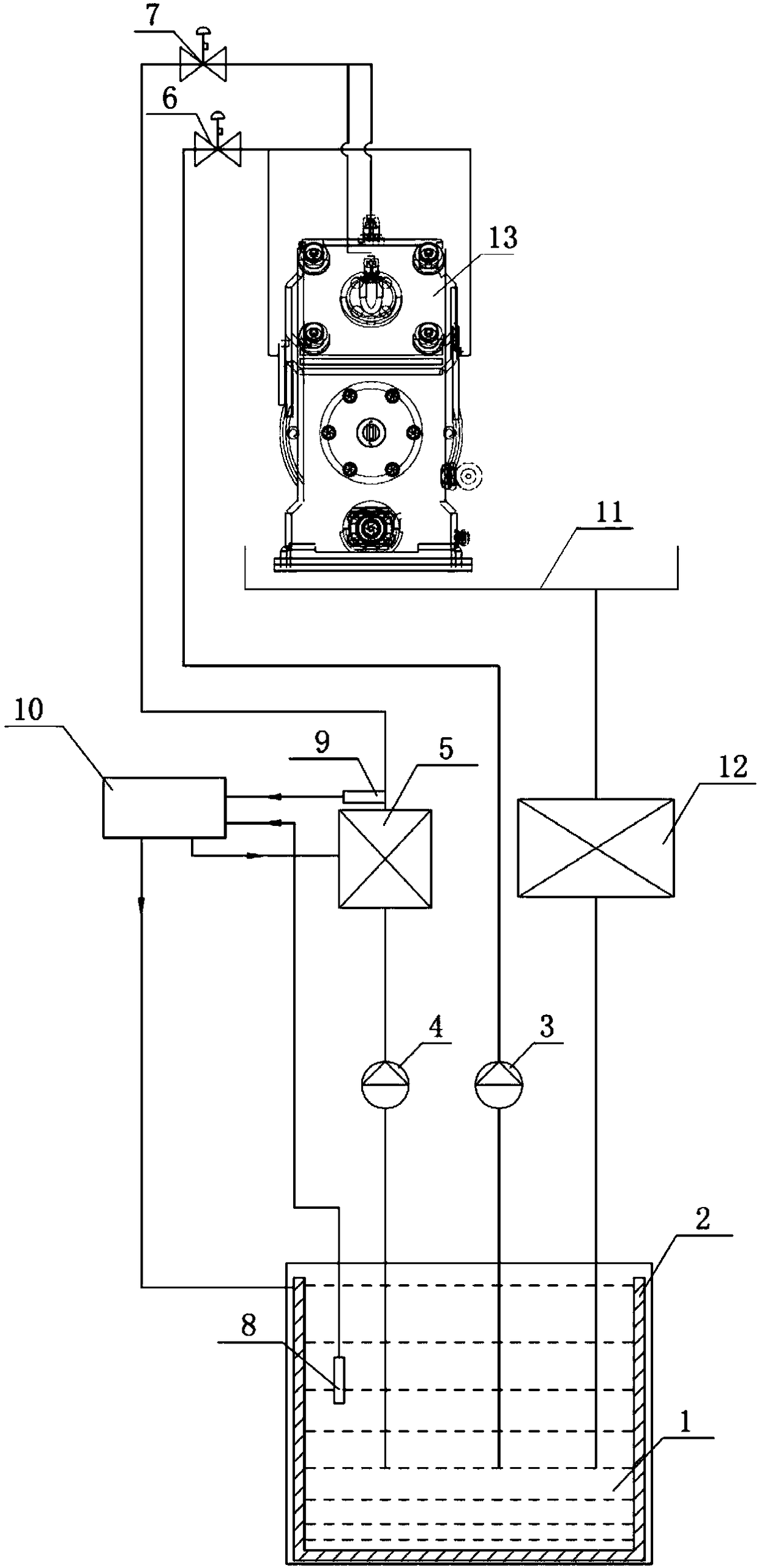
[0021] Such as figure 1 As shown, a cooling system of a three-roll mill for rolling aluminum alloy rods; including an emulsion tank 1, a heating device 2, a first emulsion circulation pump 3, a second emulsion circulation pump 4, a cooling device 5, a first valve 6 and second valve 7;

[0022] The heating device 2 is arranged in the emulsion tank 1;

[0023] The first emulsion circulation pump 3 and the second emulsion circulation pump 4 communicate with the emulsion tank 1 through pipelines, and the outlet of the first emulsion circulation pump 3 communicates with the first valve 6 through pipelines Connected, the outlet of the first valve 6 communicates with the pipeline used for cooling and lubricating the rolls and the import and export guide positions in the three-roll rolling mill 13;

[00...


PUM


Abstract

The invention discloses a cooling system of a three-roller rolling mill for a rolled aluminum alloy rod. The system comprises an emulsion box, a heating device, a first emulsion circulating pump, a second emulsion circulating pump, a cooling device, a first valve and a second valve; the first emulsion circulating pump and the second emulsion circulating pump are communicated with the emulsion boxthrough pipelines, and a flow outlet of the first emulsion circulating pump is communicated with the first valve through the pipelines; a flow outlet of the first valve is communicated with the pipelines of a roller and an inlet and outlet guide in the three-roller rolling mill, wherein the roller and an inlet and outlet guide are subject to cooling and lubricating; a flow outlet of the second emulsion circulating pump is communicated with the cooling device through the pipelines, and a flow outlet of the cooling device is communicated with the second valve through the pipelines; and a flow outlet of the second valve is communicated with the pipelines of a lubricating bearing and a gear in the three-roller rolling mill, wherein the lubricating bearing and the gear are subject to the cooling and the lubricating. The temperature drop degree of the roller and a blank can be reduced, and the damage frequency of the bearing and the gear is lowered when the three-roller rolling mill is usedfor rolling the aluminum alloy with relatively strong deformation resistance at a high temperature.

Description

technical field [0001] The invention relates to the field of rolling mill cooling systems, in particular to a cooling system of a three-roll rolling mill for rolling aluminum alloy rods. Background technique [0002] During the processing of aluminum alloy rods, the rolling force will be transmitted to the bearings and gears installed on the frame by the rolling rollers. The bearings and gears are stressed and easily damaged due to poor cooling and lubrication. When processing aluminum alloy rods in domestic three-roll rolling mills, the oil-water separation method is generally used to use a single-way emulsion to respectively guide the rolls, the inlet and outlet positions, and the rack gears and bearings to cool and lubricate. For aluminum alloys with low resistance, the gears and bearings are less stressed and can still meet the design requirements. The frequency of damage is not high, but when the alloy with high deformation resistance is hot-rolled at a higher temperatu...

Claims


Application Information

Patent Timeline
Patent Type & Authority Applications(China)
IPC IPC(8): B21B27/06B21B13/04B21B28/00
CPCB21B13/04B21B27/06B21B28/00
Inventor 周天国柯长奋徐汉新陈田田徐瑞
Owner 江苏和拓铝线有限公司
Why Eureka
Try Eureka