Three-jaw chuck for lathe

A three-jaw chuck and chuck technology, used in chucks, turning equipment, accessories of tool holders, etc., can solve the problem of inconvenient clamping of thin-walled parts, and achieve a wide range of applications, high clamping and positioning accuracy, and convenience. clamping effect

Inactive Publication Date: 2014-03-12
SHAANXI AVIATION ELECTRICAL
View PDF8 Cites 1 Cited by
  • Summary
  • Abstract
  • Description
  • Claims
  • Application Information

AI Technical Summary

Problems solved by technology

[0007] In order to avoid the disadvantages of the prior art, the present invention proposes a three-jaw chuck for lathes, which solves the problem of inconvenient clamping of thin-walled parts on lathes. The structure is simple and the clamping is convenient, and it can be used to clamp thin-walled workpieces without Deformation, reliable clamping, high positioning accuracy

Method used


Image

  • Three-jaw chuck for lathe
  • Three-jaw chuck for lathe

Examples


Embodiment Construction

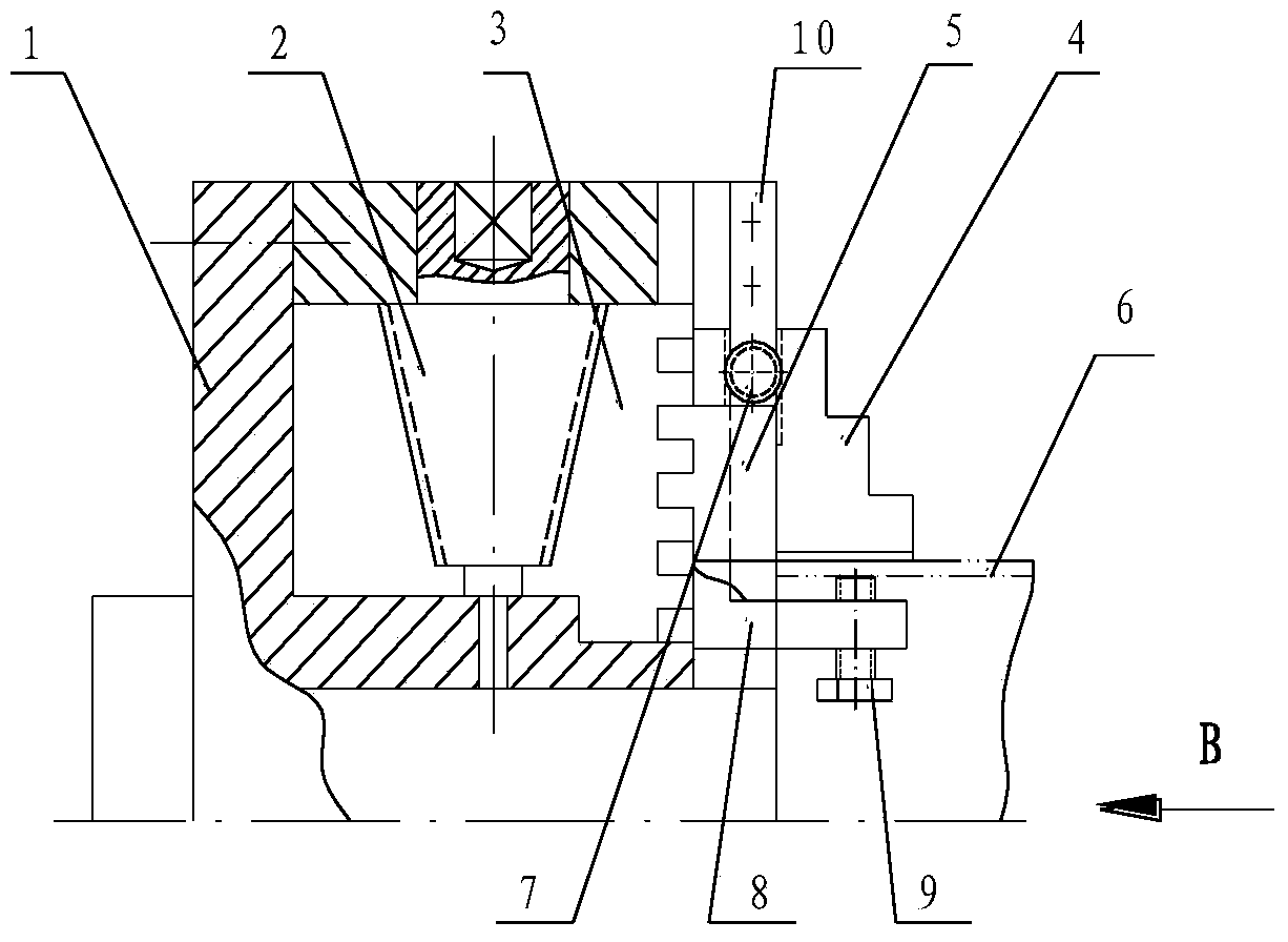
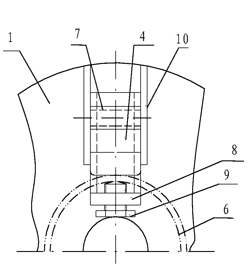
[0018] Now in conjunction with embodiment, accompanying drawing, the present invention will be further described:

[0019] Such as figure 1 Shown is the sectional view of the structure embodiment of the present invention, figure 2 for yes figure 1 Partial schematic diagram in the middle B direction, it can be seen that the three-jaw chuck for lathes includes chuck body 1, movable jaw 4, small bevel gear 2, inner disk wire 3, pinion gear 7 and top jaw 8, in which: chuck body 1 Installed in the spindle hole of the lathe, there are three evenly distributed slots on the front end surface of the chuck body 1, and the three movable jaws 4 are respectively placed in the three slots on the front end of the chuck body 1, and The bottom of the claw 4 is fixedly connected with the claw mounting seat 5 installed in the card groove, and the claw mounting seat 5 cooperates with the card groove to form a moving pair, and the card groove guides the claw mounting seat 5, and the movable cla...


PUM


Abstract

The invention relates to a three-jaw chuck for a lathe. The three-jaw chuck for the lathe comprises a chuck body, three bevel pinions, a big bevel gear with threads, three movable clamping jaws and a clamping jaw installation base. The three-jaw chuck for the lathe is characterized in that the three-jaw chuck for the lathe further comprises three L-shaped top jaws and pinions; the three L-shaped top jaws are installed on three clamping grooves in the chuck body respectively and form sliding pairs with the clamping grooves; clamping groove convex edges are arranged on the two sides of each clamping groove in the chuck body, arrangement holes used for installing the pinions are formed in the clamping groove convex edges, the pinion is installed between the two convex edges of each clamping groove, one side of each pinion is meshed with racks of the movable clamping jaws, and the other sides of the pinions are meshed with the L-shaped top jaws; the positions, extending outwards, of the L-shaped top jaws are opposite to the corresponding movable clamping jaws, and spaces for clamping parts are formed between the positions, extending outwards, of the L-shaped top jaws and the movable clamping jaws. According to the three-jaw chuck for the lathe, thin-wall parts can be clamped conveniently, the clamping and locating accuracy is high, the parts do not deform, clamping is reliable, due to the fact that adjusting bolts are arranged on the outward-extending ends of the top jaws, parts of different thicknesses can be clamped, and the application range is wide.

Description

technical field [0001] The invention relates to the technical field of machine tool fixtures, in particular to a three-jaw chuck for a lathe, in particular to a composite three-jaw chuck capable of realizing self-centering. Background technique [0002] The existing three-jaw chuck for lathes consists of a chuck body, three movable jaws and a jaw driving mechanism. The chuck body is installed at the front end of the lathe spindle; In the slot, it can slide in the card slot, and cooperate with the card slot through the mounting seat at its lower part. [0003] The drive of the jaws is formed by an inner disk wire and three small bevel gears. The inner disk wire is a large bevel gear disk with an Archimedes thread on the back, meshing with three small gears; the bottom surface of the mounting seat of the three movable jaws, There are threads that mesh with the Archimedes threads on the back of the gear plate, and the three claws are equally installed on the inner disk wire th...

Claims


Application Information

Patent Timeline
Patent Type & Authority Applications(China)
IPC IPC(8): B23B31/169
CPCB23B31/16083
Inventor 宁智博冯华
Owner SHAANXI AVIATION ELECTRICAL
Why Eureka
Try Eureka