
Sealing machine with improved locking mechanism

A locking device and sealing machine technology, applied in the direction of pressurized/vaporized packaging, etc., can solve the problems that the upper cover is difficult to open, dust is easy to dirty the vacuum sealing groove, etc., to avoid elastic failure and ensure sealing Effect

Active Publication Date: 2015-04-08
XIAMEN YOUO ELECTRIC APPLIANCES
View PDF6 Cites 0 Cited by
  • Summary
  • Abstract
  • Description
  • Claims
  • Application Information

AI Technical Summary

Problems solved by technology

[0003] The purpose of the present invention is to provide a sealing machine with an improved locking device, so as to overcome the problems in the prior art that the upper cover is difficult to open after the vacuum sealing groove is vacuumized; after opening the upper cover, the problem that the vacuum sealing groove is easily dirty by dust

Method used


Image

  • Sealing machine with improved locking mechanism
  • Sealing machine with improved locking mechanism

Examples


Embodiment Construction

[0014] The specific embodiments of the present invention will be described below with reference to the drawings.

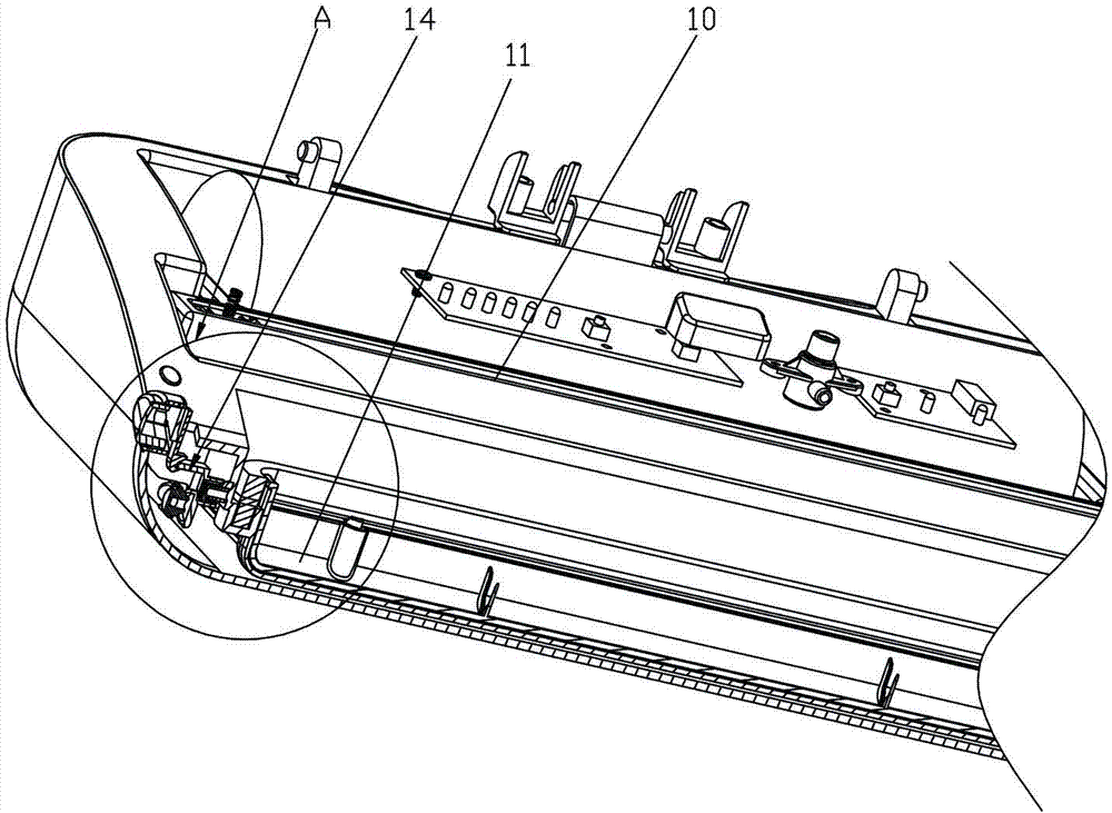
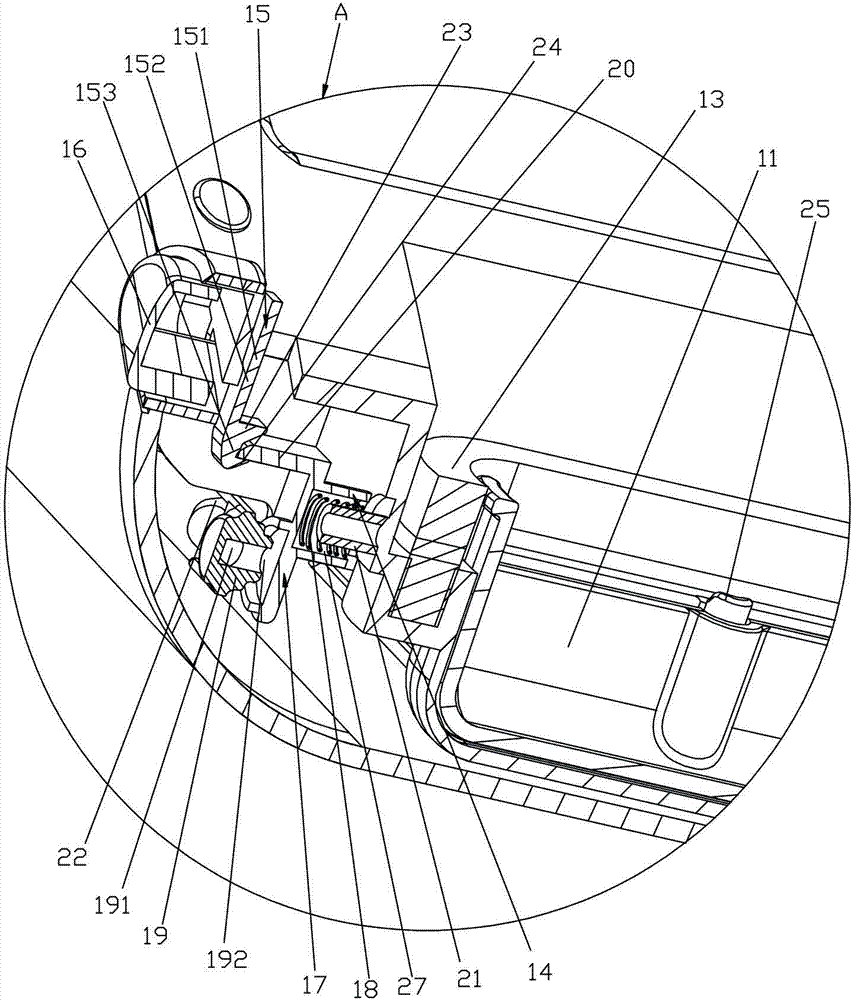
[0015] Such as figure 1 with figure 2 As shown, a sealing machine with an improved locking device includes a sealing machine main body 10 and an upper cover (not shown in the figure), and the upper cover is reversibly arranged on the sealing machine main body 10. The main body 10 of the sealing machine is provided with a first vacuum sealing groove 11, and the upper cover is correspondingly provided with a second vacuum sealing groove (not shown in the figure). The peripheral side of the first vacuum sealing groove 11 and the second vacuum sealing groove 11 The circumferential sides of the vacuum sealing groove are respectively provided with sealing rings 13. The first vacuum sealing groove 11 is connected with a vacuum device (not shown in the figure) for vacuuming air. The sealing machine also includes two locking devices 14 which are respectively installed on t...


PUM


Abstract

The invention relates to a sealing machine with an improved locking mechanism. The sealing machine comprises a sealing machine body and a top cover, the sealing machine body is provided with a first vacuumizing seal groove, the top cover is correspondingly provided with a second vacuumizing seal groove, the first vacuumizing seal groove and the second vacuumizing seal groove are respectively provided with a seal ring, the sealing machine also comprises the locking mechanisms, each locking mechanism comprises a locking hook, a press block, a push block, a spring and a communicating tube, the locking hook is connected with the top cover, the locking hook comprises a locking rod and two fastening projections, and the push block is connected with the press block and provided with a locking block. The communicating tube is provided with an air inlet and an air outlet, the air inlet of the communicating tube communicates with the first vacuumizing seal groove through a first passage, and the spring is so arranged as to push the push block toward the air outlet of the communicating tube. Dust can be prevented from entering the first vacuumizing seal groove of the sealing machine body, and moreover, the two seal rings do not squeeze each other, so that the elasticity of the seal rings is prevented from failing. Furthermore, after vacuumization is finished, the top cover can be easily opened.

Description

technical field [0001] The invention relates to a sealing machine, in particular to a sealing machine with an improved locking device. Background technique [0002] The existing sealing machine includes a main body of the sealing machine and an upper cover, the upper cover is reversibly arranged on the main body of the sealing machine, the main body of the sealing machine is provided with a vacuum sealing groove, and the upper cover is correspondingly provided with a vacuum sealing groove, the The peripheral side of the vacuum sealing groove of the main body of the sealing machine and the peripheral side of the vacuum sealing groove of the upper cover are respectively equipped with sealing rings, and the vacuum sealing groove of the main body of the sealing machine is connected with a vacuum device. When in use, place the mouth of the bag to be vacuumed in the middle of the vacuum sealing groove, and after the upper cover is closed on the main body of the sealing machine, th...

Claims


Application Information

Patent Timeline
Patent Type & Authority Patents(China)
IPC IPC(8): B65B31/04
Inventor 游图明
Owner XIAMEN YOUO ELECTRIC APPLIANCES
Learn More