Magnetic rotating shaft

A magnetic suction type, rotating shaft technology, applied in pivot connection, instruments, electrical digital data processing, etc., can solve problems such as unsightly appearance, poor compatibility between notebook base and screen connection, and achieve the effect of simple structure

Active Publication Date: 2014-03-12
HEFEI LCFC INFORMATION TECH
View PDF5 Cites 8 Cited by
  • Summary
  • Abstract
  • Description
  • Claims
  • Application Information

AI Technical Summary

Problems solved by technology

[0003] The purpose of the present invention is to solve the problem of poor compatibility and unsightly connection between the existing notebook base and the screen

Method used


Image

  • Magnetic rotating shaft
  • Magnetic rotating shaft
  • Magnetic rotating shaft

Examples


Embodiment Construction

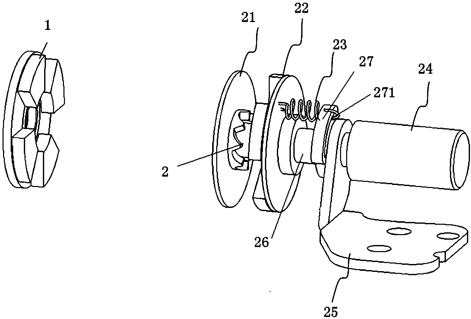
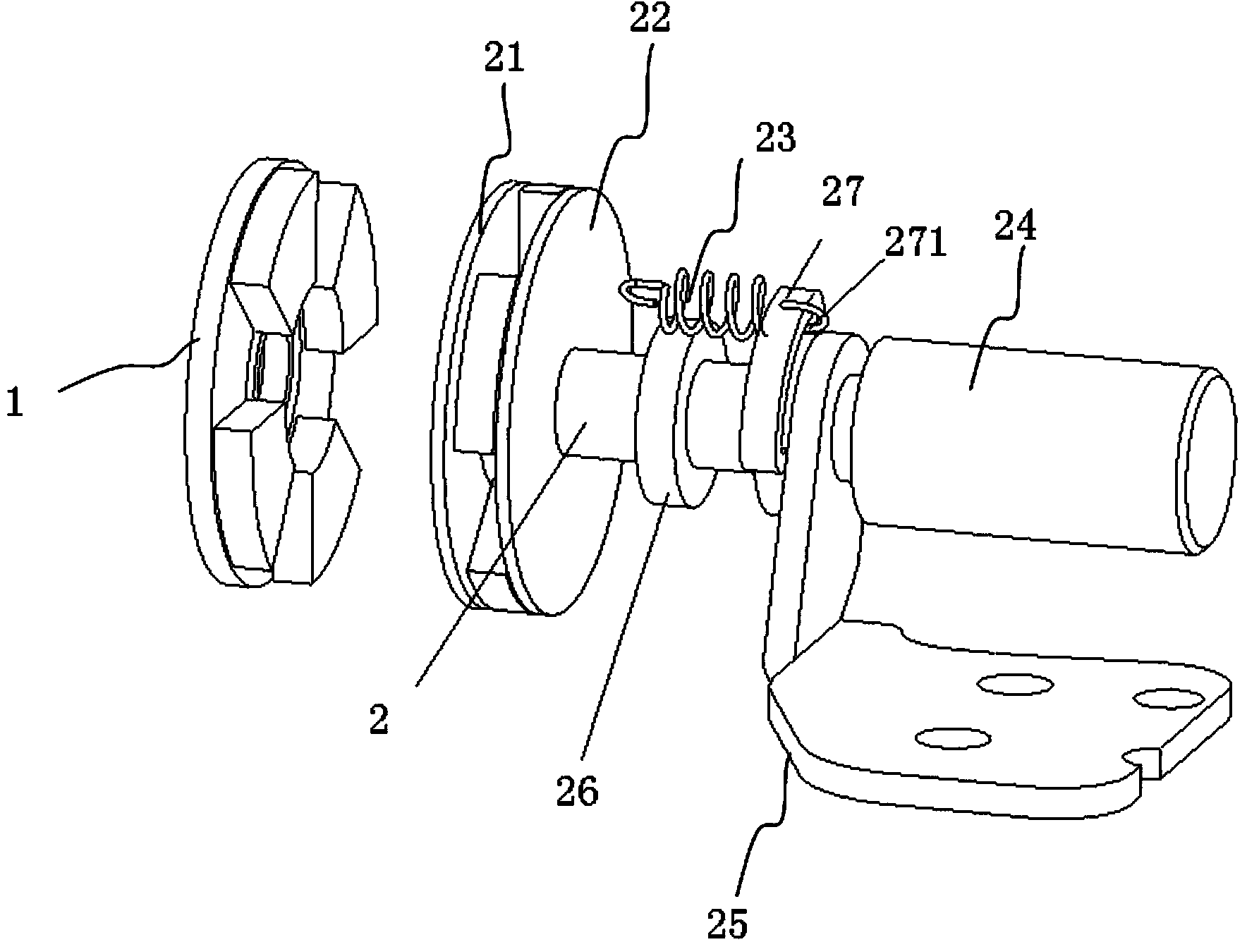
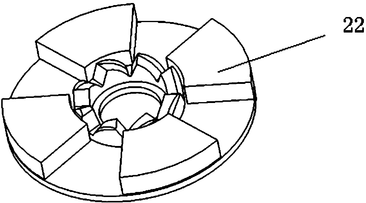
[0012] Such as figure 1 As shown, the magnetic suction type rotating shaft according to an embodiment of the present invention includes a first magnetic ring part 1 and a rotating shaft part 2, and the rotating shaft part 2 includes an engaging shaft 26 (such as Figure 4 As shown), the engaging shaft 26 includes a proximal end close to the magnetic ring part 1 and a distal end away from the magnetic ring part 1 . A radially expanding disk portion 21 is provided at the proximal end of the engaging shaft 26 , and a damper 24 is provided at the distal end to cooperate with the engaging shaft 26 to prevent the engaging shaft from pivoting. An arc groove portion 27 fixedly connected with the engaging shaft 26 is provided between the damper 24 and the disk portion 21 . Between the arc groove portion 27 and the disk portion 21, a second magnetic ring 22 (such as image 3 shown), wherein the second magnetic ring is set to have a magnetic field opposite to that of the first magnetic...


PUM


Abstract

The invention discloses a magnetic rotating shaft. The magnetic rotating shaft comprises a first magnetic ring part and a rotating shaft part, wherein the rotating shaft part comprises an engaging shaft; the engaging shaft comprises a disc-shaped part and a damper for stopping the engaging shaft from pivoting; an arc groove part fixedly connected with the engaging shaft is arranged between the damper and the disc-shaped part; a second magnetic ring in sliding fit on the engaging shaft is arranged between the arc groove part and the disc-shaped part; the magnetism of the second magnetic ring is opposite to the magnetism of the first magnetic ring; large enough attraction appears when the second magnetic ring and the first magnetic ring are close to each other by a certain distance; toothed parts which can be engaged with each other or are complementary are arranged on opposite surfaces of the second magnetic ring and the disc-shaped part; through the toothed parts thereon, the second magnetic ring and the disc-shaped part can be mutually locked in a direction around the engaging shaft; and the arc groove part is connected with the second magnetic ring through an elastic component. The magnetic rotating shaft has the advantages as follows: after adoption of the structure, the defect that in the prior art, a buckle and a hook must be matched for use, with poor compatibility, is overcome; the magnetic rotating shaft is simple in structure, so that the attractive appearance of the magnetic rotating shaft is not affected.

Description

technical field [0001] The invention relates to a connection structure between a notebook base and a screen, in particular to a magnetic connection structure. Background technique [0002] In the prior art, the connection between the notebook base and the screen usually adopts a hook structure, which is divided into two parts, which are respectively fixed on the notebook base and the screen, and the two parts are connected to each other when in use. The hook is hooked so that the base of the notebook is connected with the screen to form an integral body. This detachable hook structure requires strict alignment during assembly and disassembly to ensure that the two parts can be completely docked or separated, and this kind of hook must be used in pairs, which has poor compatibility and is not easy to install on the base of the notebook and the screen. beautiful. Contents of the invention [0003] The purpose of the present invention is to solve the problem of poor compati...

Claims


Application Information

Patent Timeline
IPC IPC(8): F16C11/12G06F1/16
Inventor 魏伟陈步林
Owner HEFEI LCFC INFORMATION TECH
Why Eureka
Try Eureka