Flywheel with variable rotational inertia

A technology of moment of inertia and flywheel, which is applied in the field of flywheel, can solve the problems of limited engine rated speed range, poor comprehensive performance of the engine, high consumption, etc., and achieve the goal of expanding the rated speed range, improving comprehensive performance and ensuring stability Effect

Active Publication Date: 2014-03-12
DFSK MOTOR LTD CHONGQING BRANCH CO
View PDF7 Cites 8 Cited by
  • Summary
  • Abstract
  • Description
  • Claims
  • Application Information

AI Technical Summary

Problems solved by technology

[0002] The flywheel is a wheel-shaped accumulator installed on the crankshaft of the engine with a large moment of inertia. When the engine speed increases, the kinetic energy of the flywheel increases to store energy; when the engine speed decreases, the kinetic energy of the flywheel decreases to release energy. It can be used to reduce the speed fluctuation of the mechanical operation process, and can store part of the energy of the engine's power stroke to overcome the resistance of other strokes and make the crankshaft rotate evenly. The greater the moment of inertia of the flywheel, the stronger its energy storage capacity , which is conducive to the smooth operation of the engine, but it needs to consume more energy to overcome the inertia energy of the flywheel during the start-up or speed change process, which reduces the flexibility of the engine. In the prior art, the flywheel is generally a fixed disc structure, and its moment of inertia is fixed. The weight of the flywheel is usually selected, which cannot effectively ensure the stability of the high-speed operation of the engine, limits the range of the engine's rated speed, and also affects the flexibility of the engine's frequent speed changes, resulting in poor overall performance of the engine and cannot meet social development. needs

Method used


Image

  • Flywheel with variable rotational inertia

Examples


Embodiment Construction

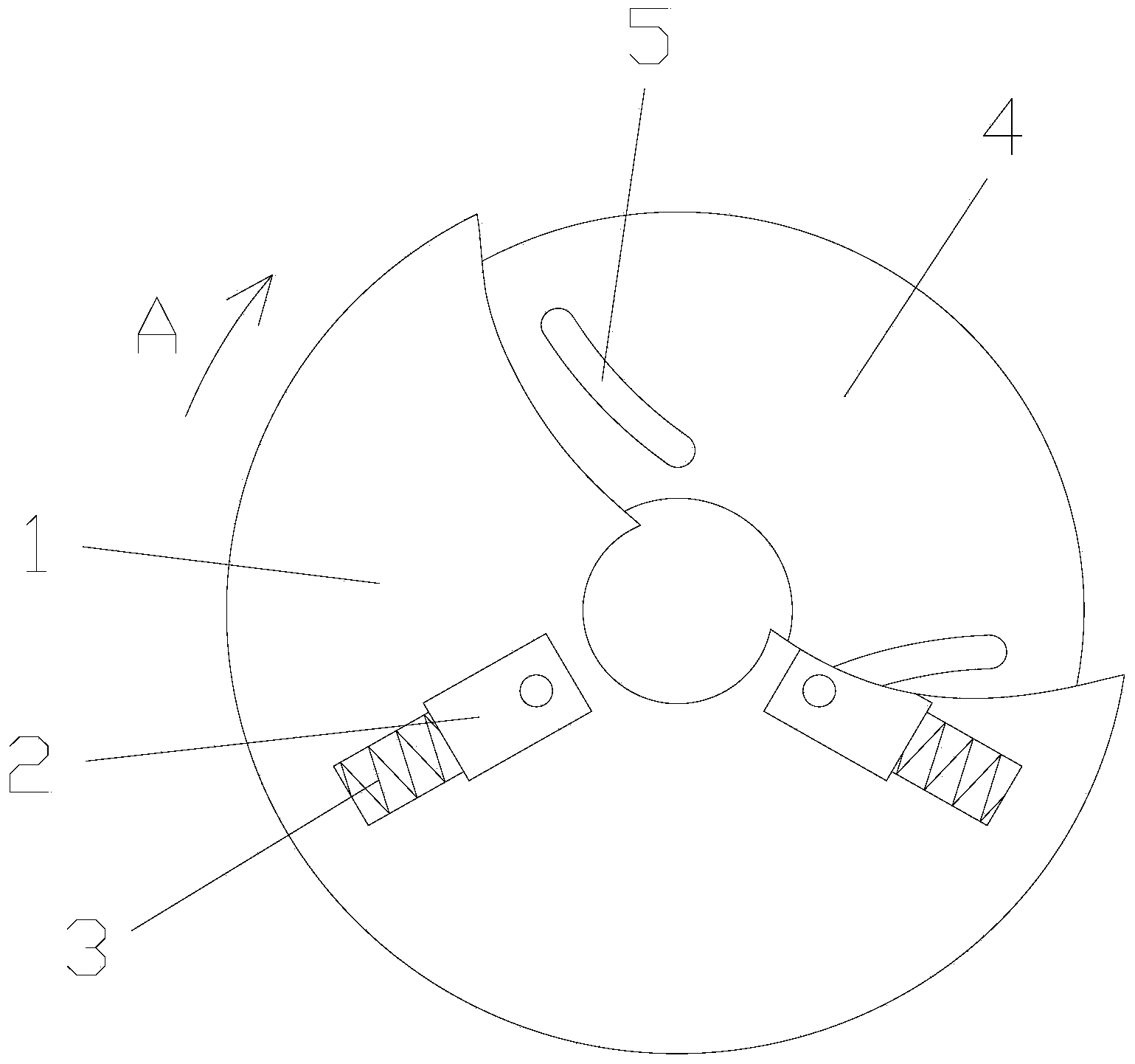
[0014] figure 1 It is a schematic diagram of the structure of the present invention, as shown in the figure: the flywheel with variable moment of inertia of the present invention includes a flywheel body 1, a slider 2 and an elastic member 3; the sliders 2 are at least two and rotate around the flywheel body 1 Evenly arranged, each slider 2 is radially slidably connected to the flywheel body 1; the elastic member 3 is connected between the slider 2 and the flywheel body 1 to provide elastic centripetal force for the slider 2, figure 1 The direction of the arrow at A in the middle is the turning direction of the flywheel body 1. Each slider 2 is arranged symmetrically around the rotation axis of the flywheel body 1. When the speed of the flywheel body 1 increases, the sliders 2 can overcome the elastic centripetal force and move radially outward along the flywheel body 1. Sliding, and then make the moment of inertia of the whole flywheel larger, otherwise make the moment of ine...


PUM


Abstract

The invention discloses a flywheel with the variable rotational inertia. The flywheel comprises a flywheel body, at least two sliding blocks and an elastic piece. The sliding blocks are evenly arranged around a rotary shaft of the flywheel body, and are connected with the flywheel body in a sliding mode in the radial direction, and the elastic piece is connected between the sliding blocks and the flywheel body and used for providing elastic centripetal force for the sliding blocks. According to the flywheel with the variable rotational inertia, the rotational inertia can be changed within certain limits along with the change of the rotation speed of an engine, stability of high-speed running of the engine can be ensured, the rated speed range of the engine can be enlarged, flexibility of frequent speed changing of the engine is improved, the comprehensive using performance of the engine is improved, and the requirements for social development can be met.

Description

technical field [0001] The invention relates to a flywheel, in particular to a flywheel with variable moment of inertia. Background technique [0002] The flywheel is a wheel-shaped accumulator installed on the crankshaft of the engine with a large moment of inertia. When the engine speed increases, the kinetic energy of the flywheel increases to store energy; when the engine speed decreases, the kinetic energy of the flywheel decreases to release energy. It can be used to reduce the speed fluctuation of the mechanical operation process, and can store part of the energy of the engine's power stroke to overcome the resistance of other strokes and make the crankshaft rotate evenly. The greater the moment of inertia of the flywheel, the stronger its energy storage capacity , which is conducive to the smooth operation of the engine, but it needs to consume more energy to overcome the inertia energy of the flywheel during the start-up or shifting process, which reduces the flexib...

Claims


Application Information

Patent Timeline
Patent Type & Authority Applications(China)
IPC IPC(8): F16F15/30F16F15/31
Inventor 张兴海
Owner DFSK MOTOR LTD CHONGQING BRANCH CO
Why Eureka
Try Eureka