Laboratory pneumatic dryer

A technology for air drying and laboratory use, applied in the field of laboratory utensils, can solve problems such as unfavorable drying rate and increase, and achieve the effect of reducing complete drying time, increasing drying rate, and drying thoroughly.

Inactive Publication Date: 2014-03-12
YIFENG CLEAN SCI & TECH JIANGSU
View PDF9 Cites 5 Cited by
  • Summary
  • Abstract
  • Description
  • Claims
  • Application Information

AI Technical Summary

Problems solved by technology

However, the air outlet holes are discretely arranged, and there are areas without air flow between the two axially adjacent air outlet holes and the circumferentially adjacent two air outlet holes, so there are dry blind areas in the axial and circumferential directions of the container to be dried, which is not necessary. Conducive to the improvement of drying rate

Method used


Image

  • Laboratory pneumatic dryer
  • Laboratory pneumatic dryer
  • Laboratory pneumatic dryer

Examples


Embodiment Construction

[0021] The present invention will now be further described in detail in conjunction with the accompanying drawings and embodiments. These drawings are all simplified schematic diagrams, only illustrating the basic structure of the present invention in a schematic manner, so it only shows the composition related to the present invention.

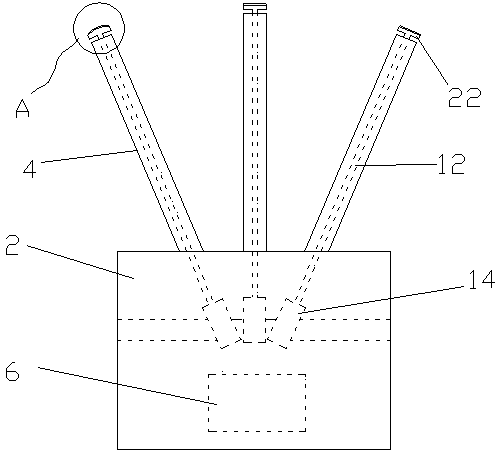
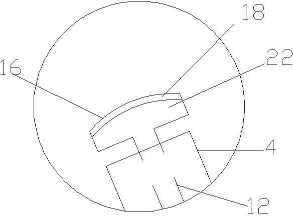
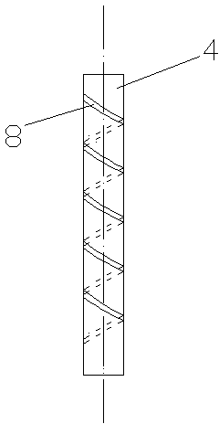
[0022] Such as Figure 1-4 As shown, a laboratory airflow dryer includes a hollow cylindrical main body 2, and several air outlet pipes 4 arranged on the main body 2, and an air supply device 6 communicating with the air outlet pipe 4 is accommodated in the main body 2 . The side wall of the air outlet pipe 4 is provided with a slit-shaped air outlet 8 , and the air outlet 8 surrounds the air outlet pipe 4 in a helical shape, and the axis coincides with the axis of the air outlet pipe 4 .

[0023] Specifically, each air outlet pipe 4 is fixed on the upper end of the main body 2 and extends radially outward. The airflow dryer of this embodim...


PUM


Abstract

The invention relates to a laboratory pneumatic dryer which comprises a hollow cylindrical main body and a plurality of air outlet pipes arranged on the main body, wherein the main body contains an air supply device communicated with the air outlet pipes. The laboratory pneumatic dryer is characterized in that the side wall of each air outlet pipe is provided with a slit-like air outlet; and the air outlet represents a helical line shape around the air outlet pipe, and the axial line of the air outlet coincides with the axial line of the air outlet pipe. According to the pneumatic dryer provided by the invention, different from the traditional hole shape, the air outlet represents a helical line shape around the air outlet pipe, thereby reducing blind zones during vessel drying, shortening the fully drying time and realizing more thorough drying.

Description

technical field [0001] The invention relates to a laboratory appliance, in particular to a dryer. Background technique [0002] The air flow dryer mainly includes the glass instrument air flow dryer used for drying glass instruments, which is a common equipment for drying glass instruments in various laboratories and laboratories. It is often used for drying test tubes, beakers, etc. It has the advantages of fast speed, energy saving, no water stains, convenient use, and simple maintenance. The existing air flow dryer includes an air supply device and an air outlet pipe. The air outlet pipe is hollow tubular, and the side wall is provided with air outlet holes. The tubular, bottle-shaped or cup-shaped container to be dried is set upside down on the air outlet pipe. The air supply device makes the air flow enter the air outlet pipe and escape through the air outlet hole to dry the inner wall of the container. However, the air outlet holes are discretely arranged, and th...

Claims


Application Information

Patent Timeline
Patent Type & Authority Applications(China)
IPC IPC(8): F26B21/00
Inventor 陆金华
Owner YIFENG CLEAN SCI & TECH JIANGSU
Why Eureka
Try Eureka