Measuring device for gap of guide blade edge plates

A technology of guide vanes and measuring devices, applied in the field of aero-engines, can solve the problems of low efficiency, restricted production, large measurement errors, etc.

Inactive Publication Date: 2014-03-12
SHENYANG LIMING AERO-ENGINE GROUP CORPORATION
View PDF7 Cites 9 Cited by
  • Summary
  • Abstract
  • Description
  • Claims
  • Application Information

AI Technical Summary

Problems solved by technology

[0002] The technology of measuring the clearance of the guide vane edge plate under the condition of applying a certain external force to the guide vane has always been a technical bottleneck that is difficult to overcome in production. This content exceeds the functions of traditional measuring devices only for positioning and pressing. meet needs
For a long

Method used


Image

  • Measuring device for gap of guide blade edge plates
  • Measuring device for gap of guide blade edge plates
  • Measuring device for gap of guide blade edge plates

Examples


Embodiment Construction

[0024] The present invention will be further described in detail below in conjunction with the accompanying drawings and specific embodiments.

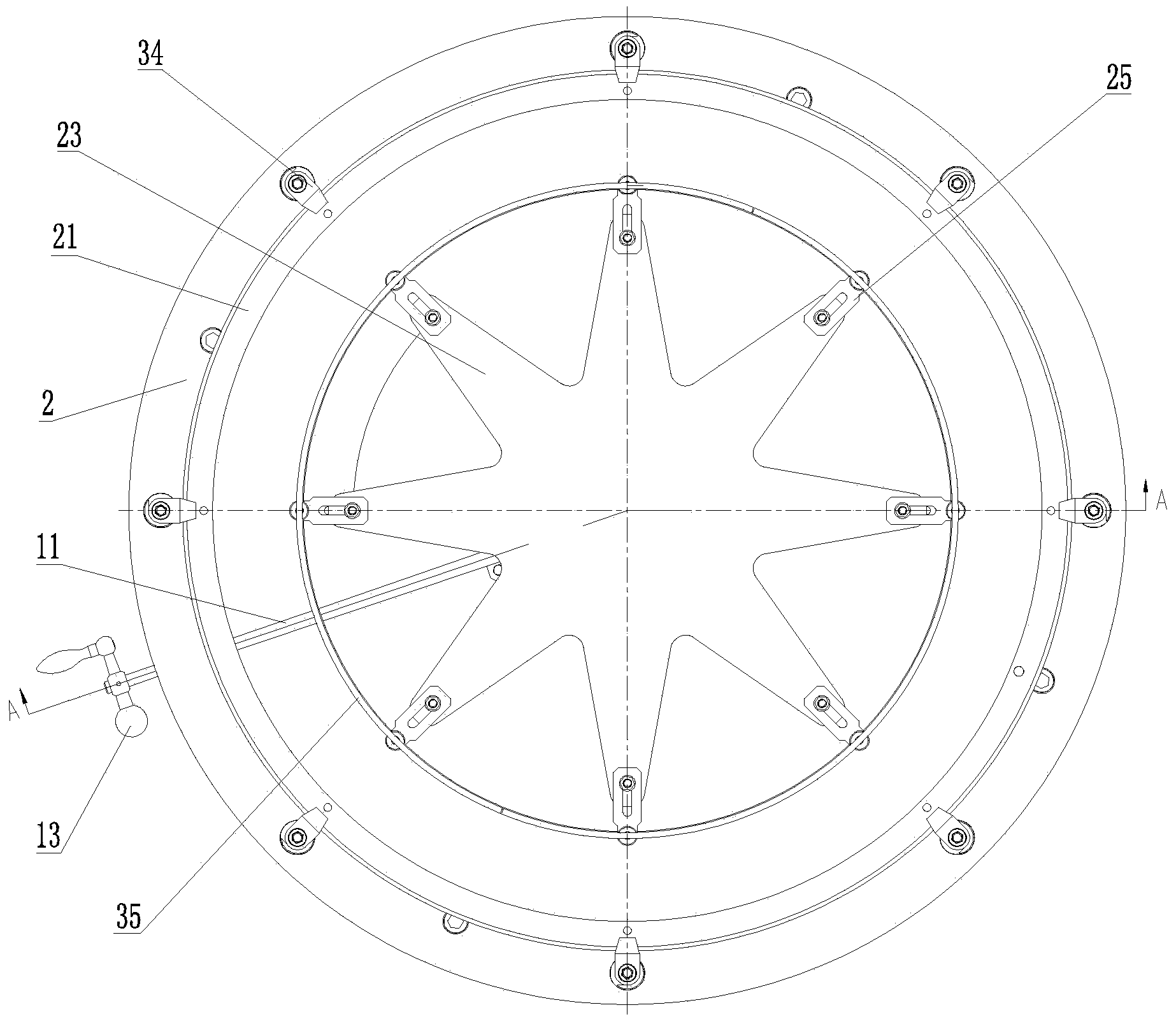
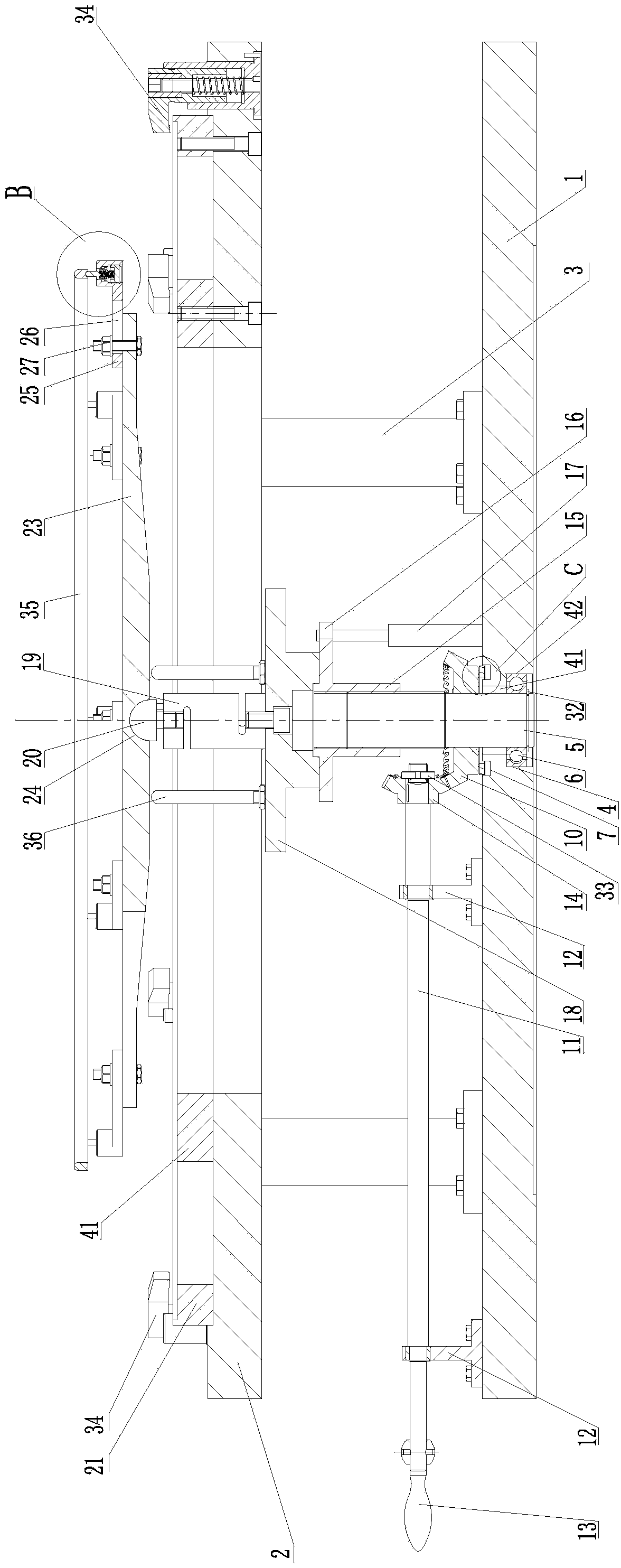
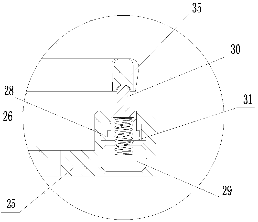
[0025] Such as Figure 1 to Figure 6As shown, a measuring device for guide vane edge plate clearance includes a chassis 1 on which a transmission mechanism, a force applying mechanism and a positioning mechanism are arranged; the transmission mechanism consists of a threaded rod 5, a screw sleeve 15, a guide pin 17, a measuring The dynamometer seat 18, the sensor 19 of the dynamometer, the pressure column 20, the angle frame 23, the guide plate 25, the thimble 30 and the support washer 35 are composed, and a through hole is arranged in the center of the chassis 1, and a threaded rod is arranged in the through hole 5, the bottom of the threaded rod 5 is connected with the chassis 1 through the bearing 6 arranged in the through hole of the chassis 1, the fit tolerance between the outer ring of the bearing 6 and the inner wall of the thr...


PUM


Abstract

A measuring device for the gap of guide blade edge plates belongs to the technical field of aviation motors. The measuring device for the gap of the guide blade edge plates is provided with a transmission mechanism, a force applying mechanism and a positioning mechanism and realizes the effect that the stable and accurate gap measuring data of the guide blade edge plates are obtained under the condition that an external force is applied to the guide blades. The device utilizes multiple uniformly distributed thimbles and a support gasket to realize the effect that the same-level guide blades are subjected to the external force with the uniform size at the same time; the design concept of piling adjusting cushion blocks is adopted, and the aim that one device is suitable for the external force applying function for the multi-level guide blades in the same receiver is realized. The measuring device comprises a chassis, wherein a lifting supporting mechanism, the force applying mechanism and the positioning mechanism are arranged on the chassis; the lifting supporting mechanism is formed by a screw rod, a screw barrel, a guide pin, a dynamometer seat, a sensor for a dynamometer, a press pillar, an angle frame, a guide plate, the thimbles and the support gasket. The force applying mechanism is formed by a first bevel gear, a second bevel gear, a rotary shaft and a support; the positioning mechanism is formed by a base with a through hole, a positioning ring and a hook-shaped press plate.

Description

technical field [0001] The invention belongs to the technical field of aero-engines, in particular to a measuring device for guide vane edge plate gaps. Background technique [0002] The technology of measuring the clearance of the guide vane edge plate under the condition of applying a certain external force to the guide vane has always been a technical bottleneck that is difficult to overcome in production. This content exceeds the functions of traditional measuring devices only for positioning and pressing. Meet the needs. For a long time, the manual traditional method is used to apply force and measure on site, requiring at least three workers to cooperate with the operation at the same time, and the method of measuring symmetrical points one by one is not only low in efficiency, but also has high labor intensity, poor stability, large measurement errors, and serious restrict production. Contents of the invention [0003] Aiming at the problems existing in the prior ...

Claims


Application Information

Patent Timeline
IPC IPC(8): G01B21/16
Inventor 秦秀秀彭会文周华锋曾庆国
Owner SHENYANG LIMING AERO-ENGINE GROUP CORPORATION
Why Eureka
Try Eureka