A camera Ptz control method and device for target tracking
A technology of target tracking and control method, which is applied in the field of camera control, can solve the problems of camera stuttering, non-smoothness, incoherence, etc., and achieves the effect of solving stuttering and incoherence.
- Summary
- Abstract
- Description
- Claims
- Application Information
AI Technical Summary
Problems solved by technology
Method used
Image
Examples
Embodiment 1
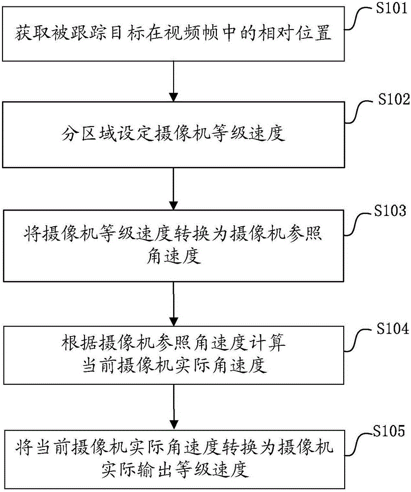
[0067] see figure 1 , which is a flow chart of a camera PTZ control method for target tracking provided by an embodiment of the present invention, specifically comprising the following steps:
[0068] S101. Obtain a relative position of a tracked target in a video frame.
[0069] In this embodiment, the relative position refers to the relative position of the tracked target in the video frame from the center point of the frame image;
[0070] The relative position in the horizontal direction of the X-axis can be calculated by the formula Calculated;
[0071] Among them, posx is the x coordinate of the point where the tracked target is located, width indicates the width of the image, and abs refers to the absolute value of the content in brackets;
[0072] The relative position in the vertical direction of the Y axis can be calculated by the formula Calculated;
[0073] Among them, posy is the y-axis coordinate of the point where the tracked target is located, and height...
Embodiment 2
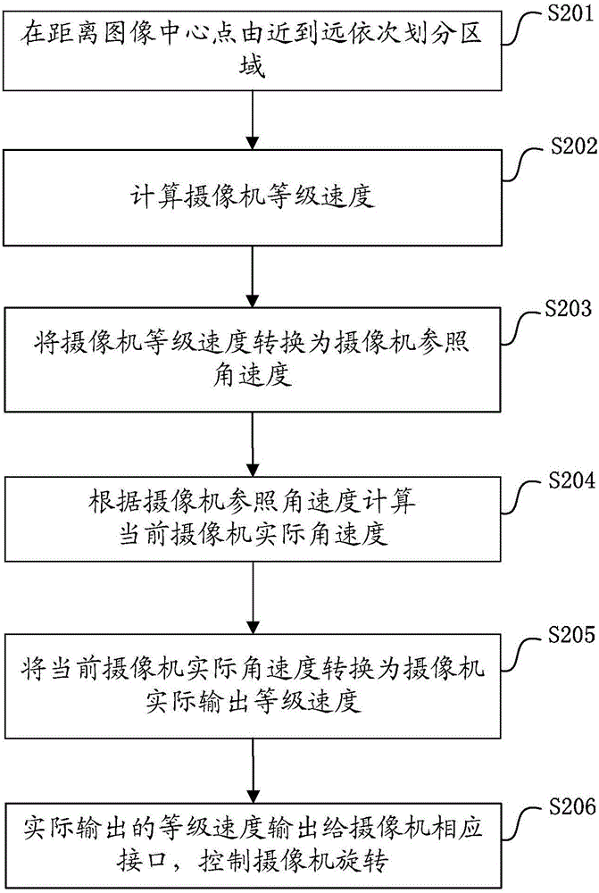
[0111] see figure 2 , the specific implementation method of the present invention will be described in detail below by taking the setting of three levels of regions in the video frame image as an example.
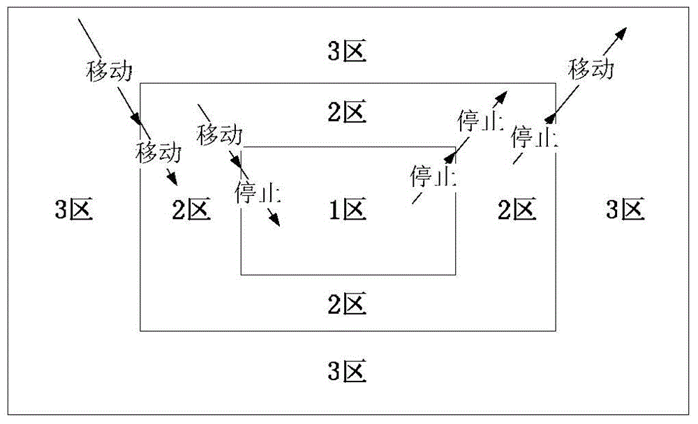
[0112] S201. Divide the first area (hereinafter referred to as area 1), the second area (hereinafter referred to as area 2), and the third area (hereinafter referred to as area 3) from near to far from the center point of the image, such as image 3 As shown, in each level region, the level speed of the camera movement is different. Intuitively, the level speed of the camera moving in the first area is lower than that in the second area, and the level speed of the camera moving in the second area is lower than that in the third area, that is, the moving speed of the camera in the third area is faster than that in the third area. Fast, while the movement speed of the camera in Zone 2 is slower than that in Zone 3, and Zone 1 is the area where the camera motion stops. In t...
Embodiment 3
[0172] The present invention also provides a camera PTZ control device for target tracking, please refer to Figure 6 , which is a schematic diagram of a camera PTZ control device for target tracking provided by an embodiment of the present invention, specifically including a target position acquisition module 601, a level speed setting module 602, an angular velocity conversion module 603, an actual angular velocity conversion module 604, and an actual level Speed conversion module 605, grade speed output module 606; the specific functions of each module are as follows:
[0173] The target position acquisition module 601 is configured to acquire the relative position of the tracked target in the video frame.
[0174] Specifically, there are two ways to select the target to be tracked, one is to manually select the target to be tracked; the other is to draw rules in the specified area, such as wandering, reverse and warning areas, when the corresponding rules are triggered ...
PUM
 Abstract
Description
Claims
Application Information
 - R&D
- Intellectual Property
- Life Sciences
- Materials
- Tech Scout
- Unparalleled Data Quality
- Higher Quality Content
- 60% Fewer Hallucinations
Browse by: Latest US Patents, China's latest patents, Technical Efficacy Thesaurus, Application Domain, Technology Topic, Popular Technical Reports.
© 2025 PatSnap. All rights reserved.Legal|Privacy policy|Modern Slavery Act Transparency Statement|Sitemap|About US| Contact US: help@patsnap.com


