Load driving device

A load-driven and pulse-driven technology, which is applied to measuring devices, logic circuit connections/interface layouts, instruments, etc., can solve problems such as pulse drive circuit failures

Active Publication Date: 2014-03-12
NGK SPARK PLUG CO LTD
View PDF5 Cites 2 Cited by
  • Summary
  • Abstract
  • Description
  • Claims
  • Application Information

AI Technical Summary

Problems solved by technology

In particular, continuous driving of resistive loads in the event of a short circuit with respect to ground potential or supply potential can lead to failure of pulsed drive circuits

Method used


Image

  • Load driving device
  • Load driving device
  • Load driving device

Examples


Embodiment Construction

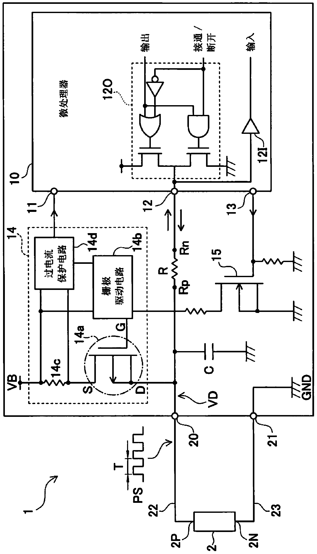
[0035] Embodiments of the present invention will be described below with reference to the drawings. figure 1 It is a figure which shows the schematic structure of the load drive apparatus 1 of this embodiment. The load driving device 1 drives a resistive load, and in this embodiment, the use of the load driving device 1 to drive a detection element (not shown) for an oxygen sensor mainly made of a solid electrolyte body such as zirconia is exemplified. The case of heater 2 for heating. Descriptions for the oxygen sensor and detection elements will be omitted.

[0036] The load driving device 1 includes a microprocessor 10 , a pulse driving circuit 14 , an FET 15 , a resistor R, and the like, and is used to drive the heater 2 .

[0037] One end 2N of the heater 2 is connected to the ground terminal 21 via the lead wire 23 , and the ground terminal 21 is grounded to the ground potential GND within the circuit of the load driving device 1 . The other end 2P of the heater 2 is ...


PUM


Abstract

A load driving device includes a pulse driving circuit which has a capacitor between an output terminal and a ground potential, a level detection circuit which detects whether an output terminal voltage on the output terminal of the pulse driving circuit is at high level or at low level, a switching discharge unit for forming a discharge path through which electric charges charged in a capacitor are discharged by switching of a switch from a non-discharge side to a discharge side, and switching the switch to the discharge side over a discharge maintenance time in a state where the application of a pulse voltage by the pulse driving circuit stops and the output terminal voltage is maintained at high level, a post-discharge detection unit, and a determination unit.

Description

technical field [0001] The present invention relates to a load driving device including a pulse driving circuit for repeatedly applying a pulse voltage to a resistive load. Background technique [0002] Generally, for example, as a load driving device that drives a resistive load such as a detection element for an oxygen sensor mainly made of a solid electrolyte body such as zirconia, a load driving device including a pulse driving circuit is used. A heater or the like for heating, and an output terminal of the pulse driving circuit are connected to the other end of a resistive load grounded at one end, and the pulse driving circuit repeatedly applies a pulse voltage to the resistive load. In this load driving device, an abnormality such as a short circuit to the ground potential or a power supply potential or a disconnection in the connection path may occur in the connection path between the pulse drive circuit and the resistive load. In particular, continuous driving of r...

Claims


Application Information

Patent Timeline
Patent Type & Authority Applications(China)
IPC IPC(8): H03K19/0175G01R31/02
CPCH03K5/19
Inventor 三野润一郎
Owner NGK SPARK PLUG CO LTD
Why Eureka
Try Eureka