Sawing wire for use in wire saw machine

A technology for sawing ropes, wire sawing machines, applied in the direction of transmission elements or pulleys with ropes or cables, mechanical equipment, belts/chains/gears, etc.

Inactive Publication Date: 2014-03-12
TYROLIT SCHLEIFMITTELWERKE SWAROVSKI KG
View PDF6 Cites 1 Cited by
  • Summary
  • Abstract
  • Description
  • Claims
  • Application Information

AI Technical Summary

Problems solved by technology

Therefore, the life of the compres

Method used


Image

  • Sawing wire for use in wire saw machine
  • Sawing wire for use in wire saw machine

Examples


Embodiment Construction

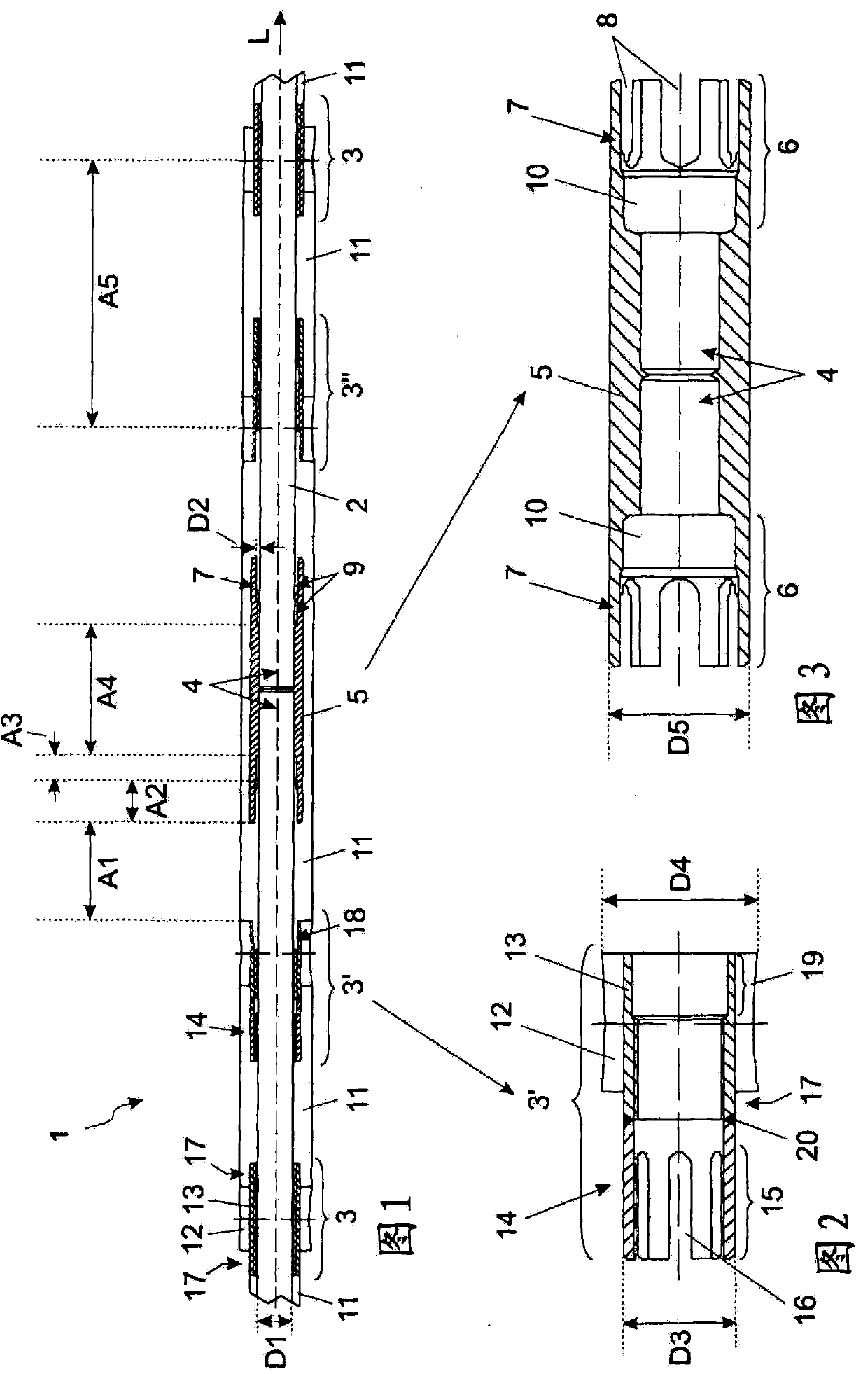
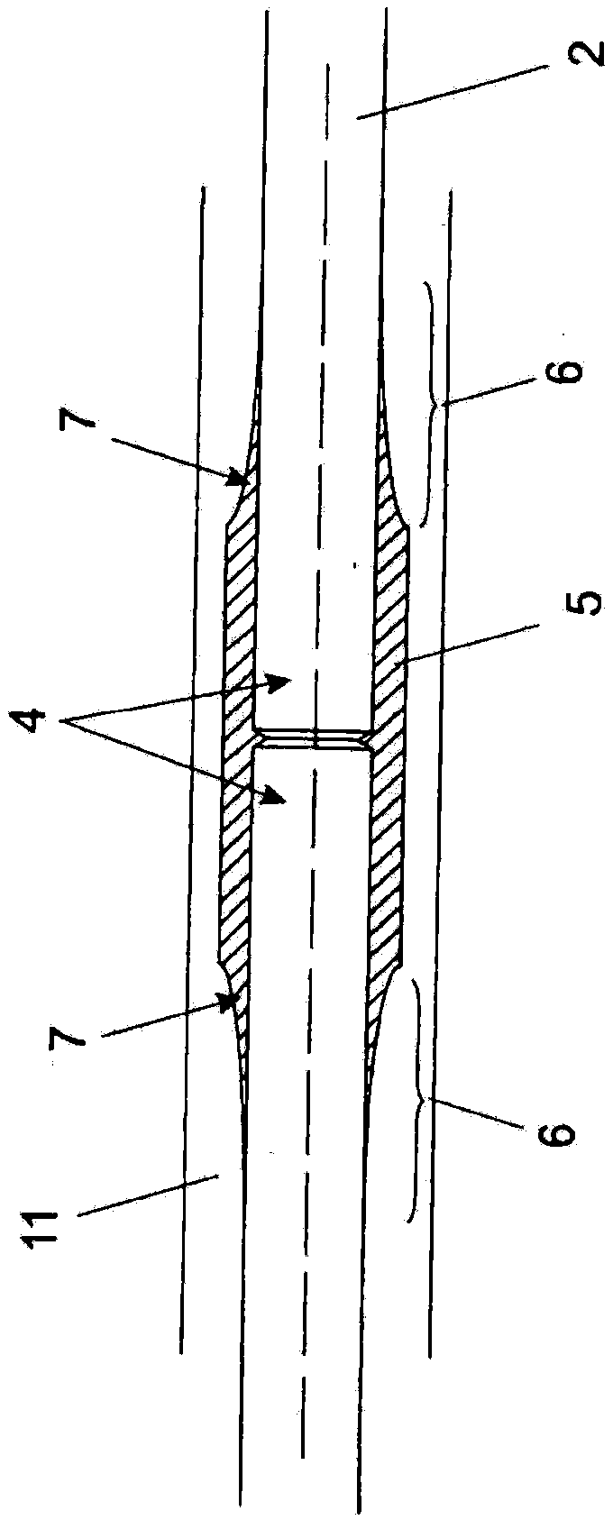
[0022] figure 1 A cross-sectional view of a section of the sawing wire 1 which is relevant for the description of the invention is shown schematically. This section can be, for example, a part of a sawing wire 1 connected to form an endless loop. Since the length of such a rope ring is usually several meters (for example, 50 meters) and figure 1 The part shown is actually only a few centimeters long, so the curvature of the sawing rope 1 cannot be seen in this figure. The partial diagram shows (viewed from the center towards the edge of the figure): a sleeve-shaped compression closure 5, by which the ends 4 of the steel wire rope 2 are connected to each other, and two sleeve-shaped compression closures 5 are connected to each other. Adjacent cutting beads 3' and 3" are structured differently from the remaining cutting beads 3, two of which are visible at the edge of the figure. All cutting beads 3, 3' and 3" are arranged on the wire rope 2. The sleeve-like compression closu...


PUM


Abstract

A sawing wire (1) for use in a wire saw machine, having a wire (2) and cutting beads (3, 3', 3'') arranged thereon, wherein the ends (4) of the wire (2) are connected to one another by a sleeve-like press closure (5), wherein the sleeve-like press closure (5) has a region of reduced rigidity at at least one end (6).

Description

technical field [0001] The invention relates to a sawing rope for use in a wire saw machine, with a steel cable and cutting beads arranged on the steel cable, wherein the ends of the steel cable are connected to each other by a sleeve-shaped compression closure. Background technique [0002] A sawing wire of interest in connection with the present invention is used in particular in wire saw machines for natural stone processing. The sawing rope essentially consists of a wire rope which consists of a plurality of individual wires which are braided together and on which cutting beads are arranged at defined distances. The cutting edge of these cutting beads usually contains a high performance cutting material such as diamond. [0003] The sawing rope is preferably used in the wire saw machine in the form of an endless loop, ie the wire rope ends must be connected to one another. A number of different closure technologies are available for this purpose, the use of sleeve-shap...

Claims


Application Information

Patent Timeline
IPC IPC(8): B28D1/12F16G11/02
CPCB28D1/124B26D1/547B28D1/08
Inventor S·克雷姆绍弗尔F·埃格
Owner TYROLIT SCHLEIFMITTELWERKE SWAROVSKI KG
Why Eureka
Try Eureka