Discrete-time filter

A discrete-time filter technology, applied in transversal filters, filters, modulation conversion of semiconductor devices with at least two electrodes, etc.

Inactive Publication Date: 2014-03-12
HUAWEI TECH CO LTD
View PDF5 Cites 9 Cited by
  • Summary
  • Abstract
  • Description
  • Claims
  • Application Information

AI Technical Summary

Problems solved by technology

In addition, the off-chip filter 1903 can only be accessed through the bond...

Method used


Image

  • Discrete-time filter
  • Discrete-time filter
  • Discrete-time filter

Examples


Embodiment Construction

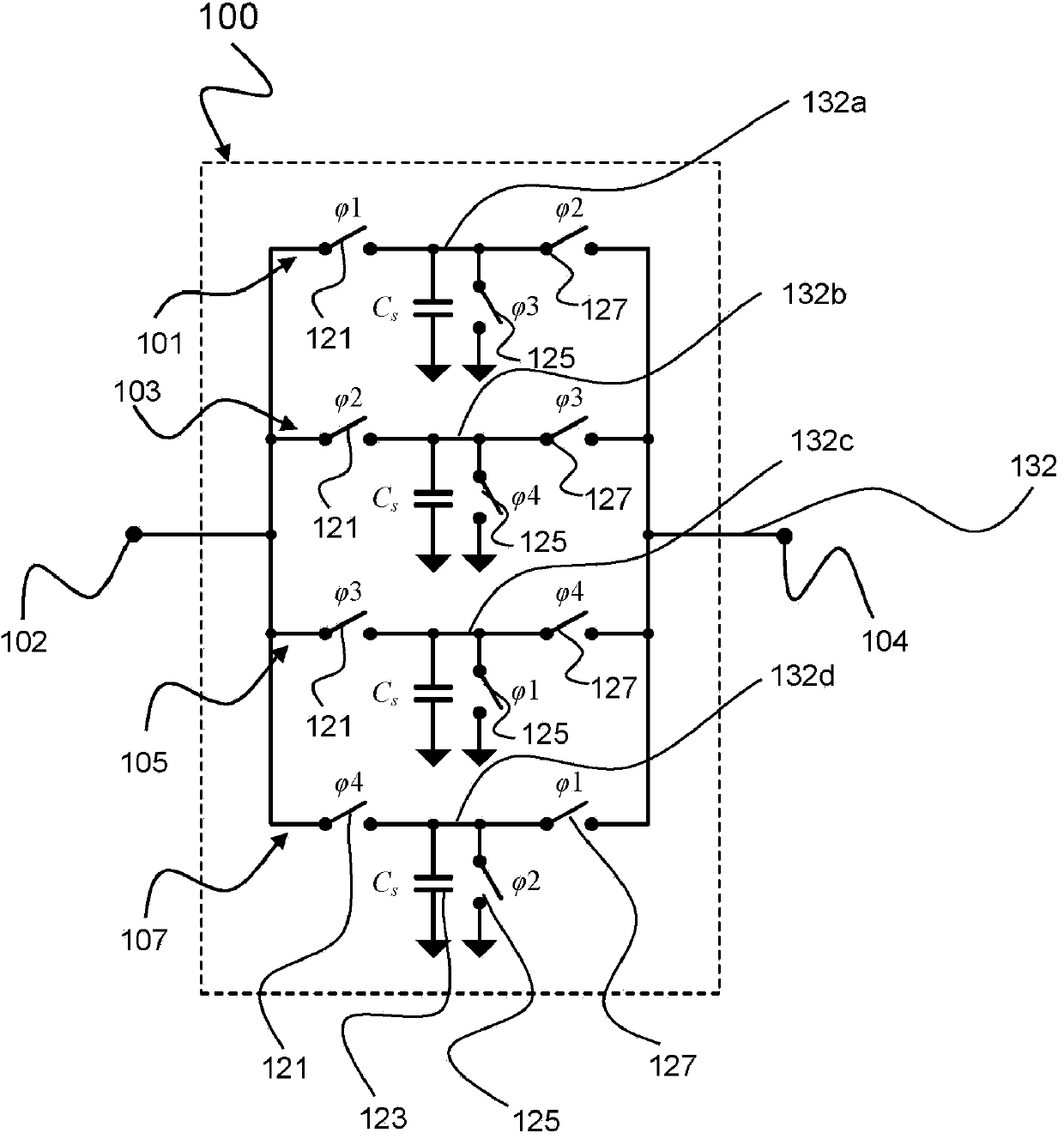
[0075] figure 1 Shown is a block diagram of a discrete-time filter 100 of the processing circuitry of a radio frequency receiver according to one form of operation. The discrete-time filter 100 includes a first switched capacitor path 101, a second switched capacitor path 103, a third switched capacitor path 105, and a fourth switched capacitor path 107, which are coupled in parallel at the input of the discrete-time filter 100 102 and output 104 between. Each of the filter paths 101, 103, 105, and 107 includes a first switch 121 coupled in series into the filter path, the input of the first switch 121 being coupled to the discrete-time filter 100 The input terminal of the capacitor 123, Cs, which connects the output terminal of the first switch 121 to the ground in parallel; the second switch 125, whose input terminal is coupled to the output terminal of the first switch 121, and whose output terminal is coupled to the ground; And a third switch 127 coupled between the inp...


PUM


Abstract

The invention relates to a discrete-time filter for filtering an input signal, the discrete-time filter comprising a switched capacitor network, the switched capacitor network comprising an input (102) and an output (104), a number of switched capacitor paths (101, 103, 105, 107) arranged in parallel between the input (102) and the output (104), each switched capacitor path (101, 103, 105, 107) comprising a capacitor, and a switch circuitry (121, 125, 127) for switching each capacitor at a different time instant for outputting a filtered input signal.

Description

technical field [0001] The invention relates to a discrete-time filter for filtering an input signal. Background technique [0002] A receiver is an electronic circuit that receives a high frequency RF signal and downconverts the RF signal to baseband for further processing and demodulation. These receivers typically amplify the weak desired RF signal and filter out unwanted adjacent signals and associated blockers. A receiver can typically be tuned to receive a particular channel in a certain frequency band by changing the LO frequency of the receiver's local oscillator. [0003] A multiband receiver can receive signals from two or more different frequency bands with different frequencies. Because these frequency bands may be far apart from each other, a multiband receiver should be tunable or programmable to cover all desired frequency bands. [0004] A multi-standard receiver can receive signals of different standards. One of the main differences between these standar...

Claims


Application Information

Patent Timeline
IPC IPC(8): H03H15/00H03D7/12
CPCH03D7/125H03H15/023H03D2200/0074H03D7/165H03D2200/006H03H11/04
Inventor 马苏德·图希迪安伊曼·麦达迪罗伯特·博丹·斯达世斯基
Owner HUAWEI TECH CO LTD
Why Eureka
Try Eureka