Shaft clamping device

A clamping device and clamping jaw technology, applied in the field of shaft clamping devices, can solve problems such as inaccurate positioning of workpieces

Inactive Publication Date: 2014-03-19
CHONGQING JIANWEI MACHINERY
View PDF0 Cites 15 Cited by
  • Summary
  • Abstract
  • Description
  • Claims
  • Application Information

AI Technical Summary

Problems solved by technology

[0003] The invention provides a shaft clamping device to solve the problem of inaccurate positioning of the workpiece existing in the existing clamping device

Method used


Image

  • Shaft clamping device

Examples


Embodiment Construction

[0010] Below in conjunction with accompanying drawing and specific embodiment the present invention will be described in further detail:

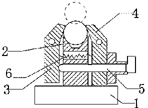
[0011] Such as figure 1 The shaft clamping device shown includes a base 1, a clamping platform 2, a first jaw 3, a second jaw 4, a force applying rod 5 and a return spring 6, the base is arranged on a guide rail, and the base can be It moves along the guide rail and locks itself, so that for some workpieces that are inconvenient to carry and move, such as workpieces that are too long, the workpiece can be clamped by moving the base to the workpiece position. The upper part of the clamping table 2 has a V-shaped groove clamp The first clamping jaw 3 and the second clamping jaw 4 are respectively arranged on both sides of the groove wall of the groove, and the upper parts of the first clamping jaw 3 and the second clamping jaw 4 all have hook-shaped clamping ends. The middle part of the claw 3 is hinged, and a first through hole is provided ...


PUM


Abstract

The invention discloses a shaft clamping device, and aims to solve the problem that workpieces cannot be accurately positioned by the aid of an existing clamping device. The clamping device comprises a base and a clamping table. The clamping device is characterized by further comprising a first clamping jaw, a second clamping jaw and a force application rod, a clamping portion with a V-shaped groove is arranged on the upper portion of the clamping table, the first clamping jaw and the second clamping jaw are arranged on two sides of the groove wall of the groove respectively, hooked clamping ends are arranged on the upper portions of the first clamping jaw and the second clamping jaw, the middle of the first clamping jaw is hinged to the base, a first through hole is formed in the clamping table, the force application rod penetrates the through hole, one end of the force application rod is fixedly connected with the lower portion of the first clamping jaw, the other end of the force application rod is in slide fit with the lower portion of the second clamping jaw, and the second clamping jaw is fixed on the base. The shaft workpieces are collectively clamped and positioned by the clamping portion with the V-shaped groove and the hooked clamping ends of the two clamping jaws, and clamping and positioning accuracy can be ensured.

Description

technical field [0001] The invention relates to machining technology, in particular to a shaft clamping device. Background technique [0002] Clamping devices are widely used in the processing and manufacturing of workpieces. at present. The clamping device for drilling shaft workpieces often has the following problems: due to the inaccurate positioning of the workpiece by the clamp, in single-piece and small-batch production, due to the inaccurate clamping and positioning, it often depends on the operator during the drilling process. Constantly manually correct the clamping device before drilling, reducing the processing efficiency of the workpiece. Contents of the invention [0003] The invention provides a shaft clamping device to solve the problem of inaccurate positioning of a workpiece existing in the existing clamping device. [0004] In order to solve the above technical problems, the present invention adopts the following technical solutions: [0005] The cl...

Claims


Application Information

Patent Timeline
Patent Type & Authority Applications(China)
IPC IPC(8): B23B47/00B23Q3/06
CPCB23Q3/062
Inventor 江伟
Owner CHONGQING JIANWEI MACHINERY
Why Eureka
Try Eureka