Thin-walled cylinder body welding and shaping clamp

A thin-walled cylinder and shape-calibrating technology, which is applied in welding equipment, auxiliary welding equipment, welding/cutting auxiliary equipment, etc., can solve problems such as increased welding and forming costs, difficult processing quality, and inconvenient operation, and achieves The effect of weight reduction, high versatility, and easy operation

Active Publication Date: 2014-03-19
AECC AERO SCI & TECH CO LTD
View PDF6 Cites 11 Cited by
  • Summary
  • Abstract
  • Description
  • Claims
  • Application Information

AI Technical Summary

Benefits of technology

This patented device allows for precise control over how much pressure should be placed on an object being worked upon while maintaining its stability when supported at certain points. Its technical effect lies in that this device simplifies the process of creating complex shapes without requiring expensive equipment such as lasers or other tools like drilling machines.

Problems solved by technology

This technical problem addressed in this patents relates to improving the accuracy and efficiency of manufacturing processes used when weldings work with sheets made from aluminum alloys (Al) due to their unique properties such as being lightweight but resistant to corrosion compared to other materials like steel plating. Current methods involve complicated equipment that require multiple steps before they can be applied effectively without causing damage.

Method used


Image

  • Thin-walled cylinder body welding and shaping clamp
  • Thin-walled cylinder body welding and shaping clamp
  • Thin-walled cylinder body welding and shaping clamp

Examples


Embodiment Construction

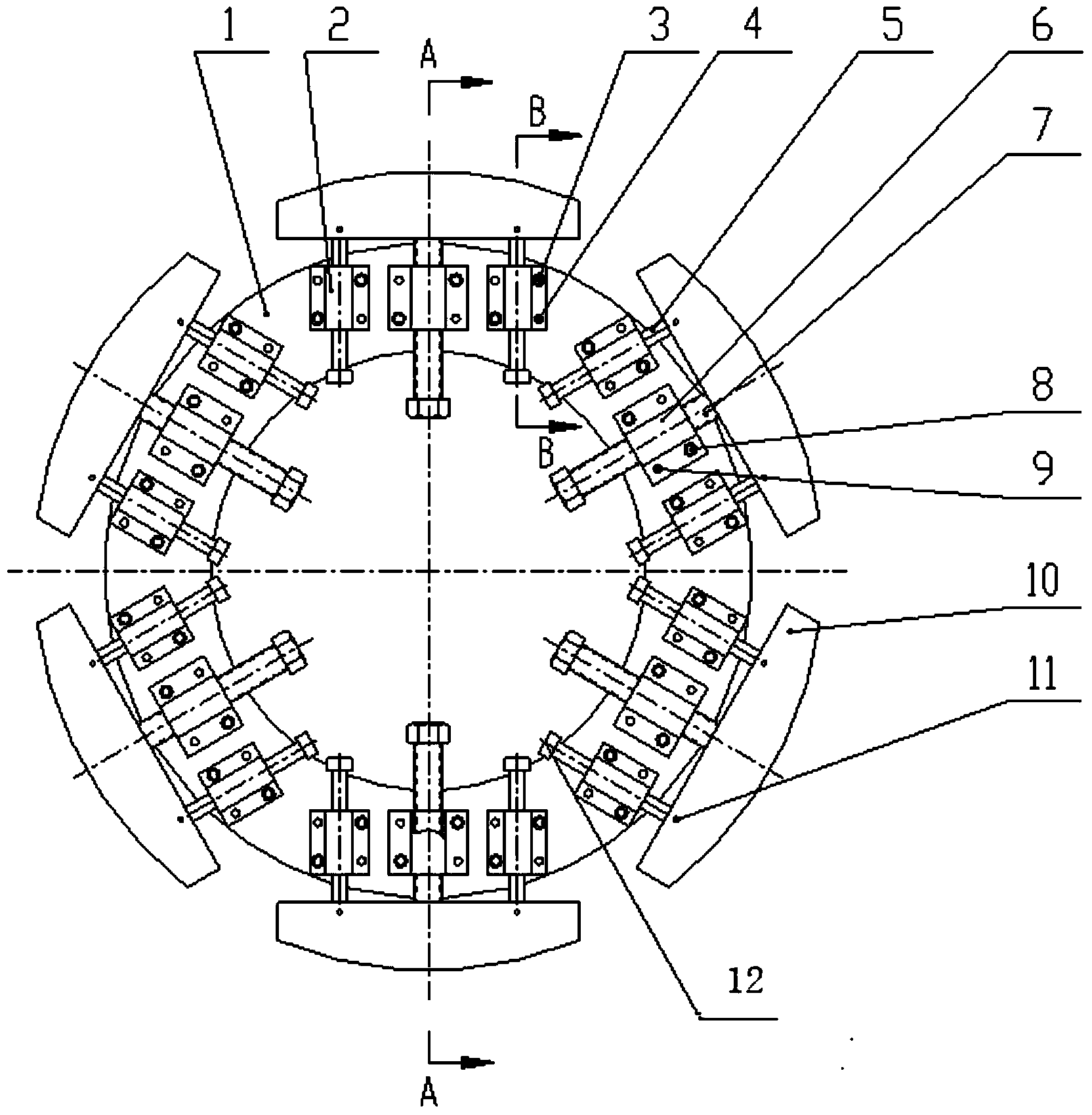
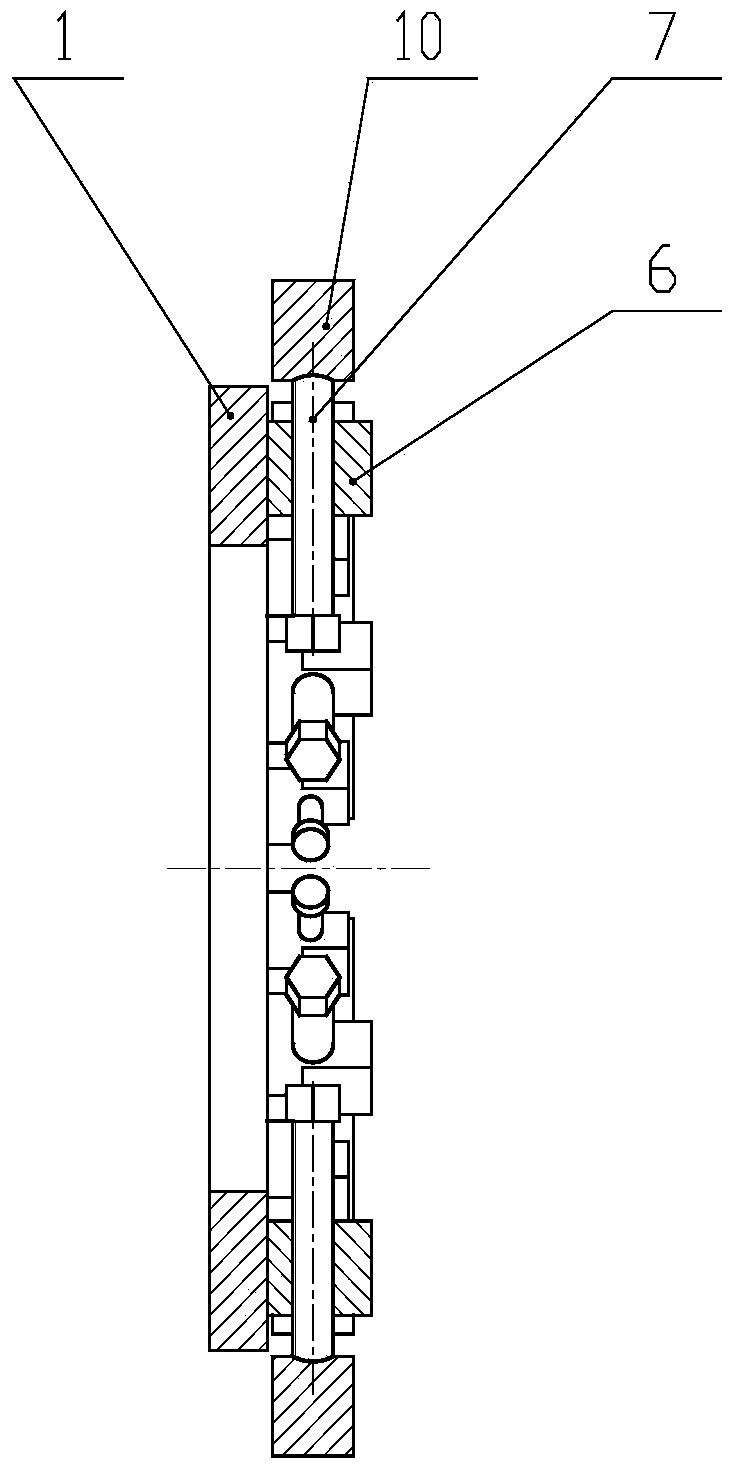
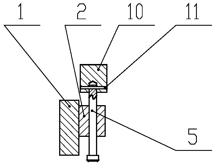
[0033] The structure of the thin-walled cylinder welding and shape-correcting jig according to the present invention will be further described below through examples and in conjunction with the accompanying drawings.

[0034] In this embodiment, the thin-walled cylindrical body welding and shape-correcting fixture is used for welding and shape-correcting circular thin-walled cylindrical body parts, and its structure is as follows figure 1 , figure 2 , image 3 As shown, it is composed of a support ring 1, an expansion block 10, a guide assembly and a force transmission assembly; the force transmission assembly includes a first base 6 and a force transmission screw 7 installed in a screw hole provided on the first base. The guide assembly includes a second base 2 and a guide pin 5 inserted in a through hole provided on the second base, one end of the guide pin is provided with a step 12, the support ring 1 is a circular ring body, and the expansion block The outer surface of...


PUM


Abstract

The invention relates to a thin-walled cylinder body welding and shaping clamp which comprises a supporting ring, expansion blocks, guide assembles and force transmission assemblies. The force transmission assembly comprises a first base and a transmission screw which is installed in a screw hole formed in the first base. Each guide assembly comprises a second base and a guide pin which is installed in a through hole formed in the second base in an inserted mode. The number of the expansion blocks is at least three. The number of the force transmission assemblies is equal to that of the expansion blocks. Each force transmission assembly set is provided with two guide assembly sets. All the force transmission assemblies are installed on the top face of the supporting ring away from one another by the same angle. The two guide assembly sets of each force transmission assembly set are symmetrically arranged on the two sides of the force transmission assembly set. One expansion block is assembled with one force transmission assembly set. All the expansion blocks are connected with the guide pins of the guide assemblies on the two sides of the force transmission assemblies which are assembled with the expansion blocks.

Description


Claims


Application Information

Patent Timeline
Owner AECC AERO SCI & TECH CO LTD
Why Eureka
Try Eureka