Rapier side twisting device

An edger and rapier technology, applied in textile, textile, papermaking, looms and other directions, can solve the problems of reducing the service life of the linear guide 5, increasing the cost of use, accelerating the damage of the slider 4 and the linear guide 5, etc. It is easy to adjust and tighten the slider, improve the service life, and achieve the effect of excellent wear resistance.

Active Publication Date: 2014-03-19
广东康特斯织造装备有限公司
View PDF8 Cites 1 Cited by
  • Summary
  • Abstract
  • Description
  • Claims
  • Application Information

AI Technical Summary

Problems solved by technology

When the motor 1 of this type of edger moves forward and backward, the connecting rod 10 will follow the swing, thereby controlling the slider 4 and the yarn guide device 6 on the slider 4 to move up and down, but because the moving direction of the connecting rod 10 is different from that of the slider 4 The direction of movement is inconsistent, and the connecting rod 10 directly transmits power to the slider 4 through the spherical joint 20, resulting in a certain lateral impact force on the linear guide 5 during the movement of the slider 4, so that the acceleration slider 4 and the linear guide 5 are damaged.
combine Figure 4 As shown, the OA section is an eccentric section of the swing rod, which takes the O point as the center and rotates forward and reverse along the direction of the R arrow. The AFG section is the connecting rod 10, and the connecting rod 10 generates the force in the AG direction during the rotation of the swing rod. F0, F0 act directly on the GH section (that is, on the slider 4), and the slider 4 produces a component force F1 that is consistent with the axis direction of the linear guide 5 and a lateral component F2 that points to the side of the linear guide 5. Due to the lateral component F2 The existence of , resulting in damage to the acceleration slider 4 and the linear guide 5
[0003] Simultaneously, because slide block 4 and linear guide rail 5 all are the important parts of selvage device, once this part is replaced, then need thread the yarn that weaves use again, and workload is very large
In addition, most of the slide grooves on the front and rear sides of the linear guide rail 5 of the existing edge winch are T-shaped grooves 52, and the area of ​​the top surface in the T-shaped groove 52 is small, and the wear resistance is low, which reduces the service life of the linear guide rail 5. Increase the cost of use

Method used


Image

  • Rapier side twisting device
  • Rapier side twisting device
  • Rapier side twisting device

Examples


Embodiment Construction

[0029] The present invention will be further described below in conjunction with the accompanying drawings and embodiments.

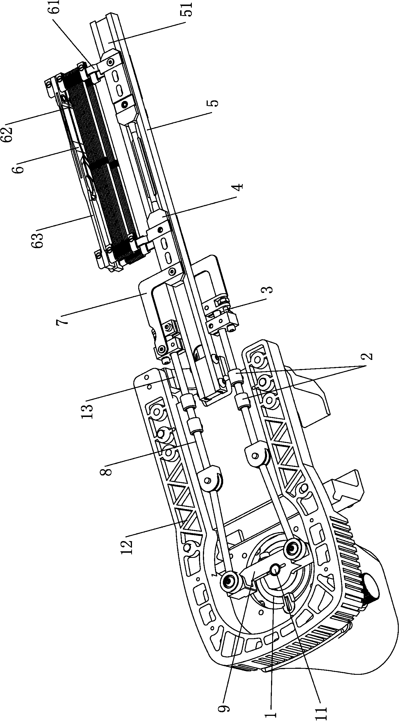
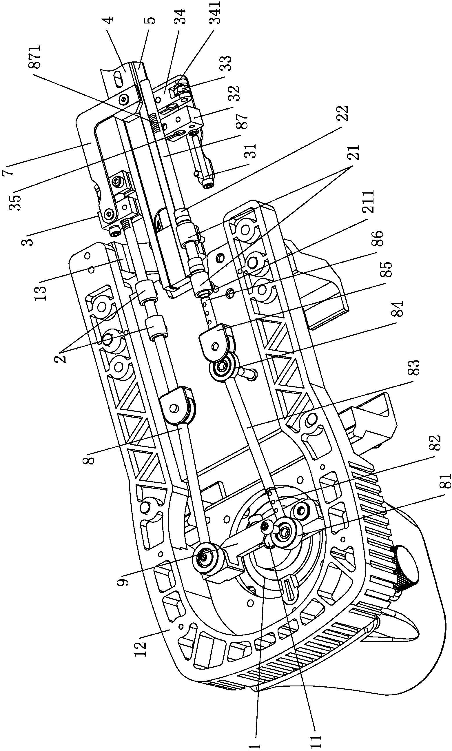
[0030] Such as figure 1 and figure 2 As shown, a rapier hemming device includes a motor 1, a linear guide rail 5, two connecting rod assemblies 8 and two yarn guide devices 6, the motor 1 is arranged on a base 12, and the rotating shaft 11 of the motor 1 is connected with a swing rod 9 , the front and rear sides of the linear guide rail 5 are respectively provided with sliders 4, and the two yarn guide devices 6 are respectively connected with a slider 4, and the two ends of the two connecting rod assemblies 8 are respectively connected with the swing rod 9 and a slider 4, and the connecting The rod assembly 8 includes a short connecting rod 83 and a sliding rod 87, one end of the short connecting rod 83 is hinged to one end of the swing rod 9, the other end of the short connecting rod 83 is hinged to one end of the sliding rod 87, and the sliding ro...


PUM


Abstract

The invention relates to a rapier side twisting device. The rapier side twisting device comprises a motor, a linear guide rail, two connecting rod assemblies and two yarn guide devices, wherein the motor is arranged on a base, a swing rod is connected to a rotating shaft of the motor, the front side and the rear side of the linear guide rail are respectively provided with a slider, the two yarn guide devices are connected with the two sliders respectively, the two ends of each connecting rod assembly are connected with the swing rod and one slider respectively, each connecting rod assembly comprises a short connecting rod and a sliding rod, one end of each short connecting rod is hinged to the eccentric position of the swing rod, the other end of each short connecting rod is hinged to one end of the corresponding sliding rod, the sliding rods are arranged on the base in a sliding mode in the direction of the axis of the linear guide rail, and the other end of each sliding rod is connected with the corresponding slider. According to the side twisting device, due to the fact that the connecting rod assemblies are changed into two-segmentation structures in which the short connecting rods are hinged to the sliding rods (an existing structure is a one-segmentation transmission structure), the moving direction of the sliding rods on the base is limited to be consistent with the moving direction of the sliders through guide assemblies, and therefore cross component force of important part sliders (side twisting actuating parts) in the side twisting device is not applied to the linear guide rail, and the service life of the rapier side twisting device is prolonged.

Description

technical field [0001] The invention relates to the technical field of textile machinery, in particular to a rapier edger for a rapier loom. Background technique [0002] see Figure 5 , which is an existing rapier edger, which includes a motor 1, a linear guide rail 5, two connecting rods 10 and two yarn guide devices 6, a swing bar is connected to the rotating shaft of the motor 1, and slide rails are respectively provided on the front and rear sides of the linear guide rail 5. Block 4, two yarn guiding devices 6 are respectively connected with a slider 4, the middle section of the connecting rod 10 is provided with a curved position, the two ends of the two connecting rods 10 are respectively connected with two eccentric parts of the swing rod, and the other part of the connecting rod One end connects with the connecting arm 7 on the slider 4 through a spherical joint 20 . When the motor 1 of this type of edger moves forward and backward, the connecting rod 10 will follo...

Claims


Application Information

Patent Timeline
IPC IPC(8): D03D47/40D03C7/00
Inventor 彭长林夏云科范文博戴晓晗陈益杰关玉芹申利琼刘志远成小军
Owner 广东康特斯织造装备有限公司
Why Eureka
Try Eureka