Building material conveying device

A technology for conveying devices and building materials, applied in the processing of building materials, construction, building construction, etc., can solve problems such as low efficiency, high construction costs, complex structures, etc., and achieve the effect of good slip and improved reliability

Active Publication Date: 2014-03-19
JINLING INST OF TECH
View PDF4 Cites 3 Cited by
  • Summary
  • Abstract
  • Description
  • Claims
  • Application Information

AI Technical Summary

Problems solved by technology

[0003] The object of the present invention is to provide a building material conveying device to solve the problems of time-consuming, laborious and inefficient existing in the building material conveying methods in the prior art, and overcome the defects of complex structure, large energy consumption and high construction cost. Meet the needs of actual construction conditions

Method used


Image

  • Building material conveying device
  • Building material conveying device

Examples


Embodiment 1

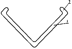
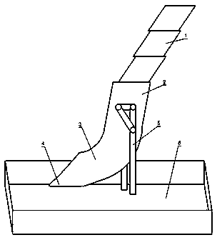
[0042] A construction material conveying device, comprising a conveying unit and a collecting unit 6 connected to the conveying unit; In the direction from top to bottom, the structure is drawn layer by layer from the inner layer to the outer layer, wherein the inner surface of the innermost pull plate 1 is smooth, and the outer surface is provided with sliding and pulling ribs along the vertical direction. Wherein the inner surface of the outermost drawing board 1 is provided with a sliding drawing groove along the vertical direction, and the outer surface is smooth, and the outer surface of the drawing board 1 of the other middle layer is provided with a sliding drawing groove along the vertical direction. Pull convex flute, the inner surface is provided with sliding and pulling grooves along the vertical direction.

Embodiment 2

[0044] A kind of construction material conveying device, with the embodiment 1, the difference is that the sliding and pulling ribs provided on the outer surface of the pulling plate 1 of the innermost layer and the middle layer are set as T-shaped, and the middle layer and the middle layer The size of the sliding and drawing groove provided on the inner surface of the outermost drawing plate 1 matches the upper end transverse dimension of the T-shaped sliding and drawing convex corrugation.

Embodiment 3

[0046] A construction material conveying device, the difference is that the middle layer and the outermost layer of the pull plate 1 are provided with stoppers on both sides of the bottom of the sliding pull groove on the inner surface, The gap distance between the edges of the two side blocks matches with the lower end transverse dimension of the T-shaped sliding and pulling ribs.


PUM


Abstract

The invention relates to a building material conveying device which comprises a conveying unit and a collecting unit connected with the conveying unit, wherein the conveying unit comprises multiple layers of stacked push-pull plates which can be pushed and pulled layer by layer from the inner layer to the outer layer in a top to down direction, wherein the inner surface of a push-pull plate on the innermost layer is smooth, and a sliding push-pull raised ridge is formed on the outer surface in the vertical direction; a sliding push-pull groove is formed in the inner surface of a push-pull plate on the outermost layer in the vertical direction, and the outer surface is smooth; and sliding push-pull raised ridges are formed on the outer surfaces of the rest push-pull plates on the middle layer in the vertical direction, and sliding push-pull grooves are formed in the inner surfaces of the push-pull plates in the vertical direction. The problems of time consumption, labor consumption and lower efficiency of a conventional building material conveying method can be solved, the defects of complicated structure, larger energy consumption and high construction cost are overcome, and the building material conveying device has the advantages of simple and ingenious structure, convenience and safety in use and capability of improving construction efficiency and safety, and can meet requirements of actual construction conditions.

Description

technical field [0001] The invention belongs to the technical field of construction equipment, and relates to a conveying device, in particular to a building material conveying device. Background technique [0002] At present, in the process of building construction, the remaining building materials or construction waste generated during the construction of high-rise buildings are mostly transported to the ground by lifts or elevators, and then sorted and cleaned. This requires construction personnel to specifically place the building materials or construction waste It is time-consuming and labor-intensive to put or put into the elevator or elevator, and the transportation volume and transportation efficiency are also seriously affected by the capacity and lifting efficiency of the elevator or elevator, which is difficult to meet the needs of efficient construction. In addition, because the elevator or elevator is used for transportation, There are also the problems of compl...

Claims


Application Information

Patent Timeline
Patent Type & Authority Applications(China)
IPC IPC(8): E04G21/00
Inventor 王潘绣
Owner JINLING INST OF TECH
Why Eureka
Try Eureka