
Wind wheel locking device of megawatt-level wind driven generator

A technology for wind turbines and locking devices, which is applied to wind turbine components, wind turbines, wind power generation, etc., can solve the problems of inability to guarantee the best position of the manhole, increasing the risk factor, and low hole alignment accuracy.

Active Publication Date: 2014-03-19
上海华仪风能电气有限公司
View PDF7 Cites 19 Cited by
  • Summary
  • Abstract
  • Description
  • Claims
  • Application Information

AI Technical Summary

Problems solved by technology

However, this technology requires manual locking and unlocking, and the workload is heavy. Because the lock hole is very close to the wind wheel, the risk factor is increased; when the lock hole is locked, it is necessary to manually find the hole position of the wind wheel lock plate, and manual turning The wind rotor has low hole alignment accuracy and the random position of the wind rotor, which cannot guarantee the best position to enter the inspection hole. It is not suitable for wind turbines with larger MW-level single-unit capacity

Method used


Image

  • Wind wheel locking device of megawatt-level wind driven generator
  • Wind wheel locking device of megawatt-level wind driven generator
  • Wind wheel locking device of megawatt-level wind driven generator

Examples


Embodiment 1

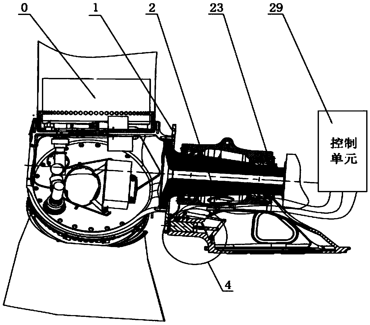
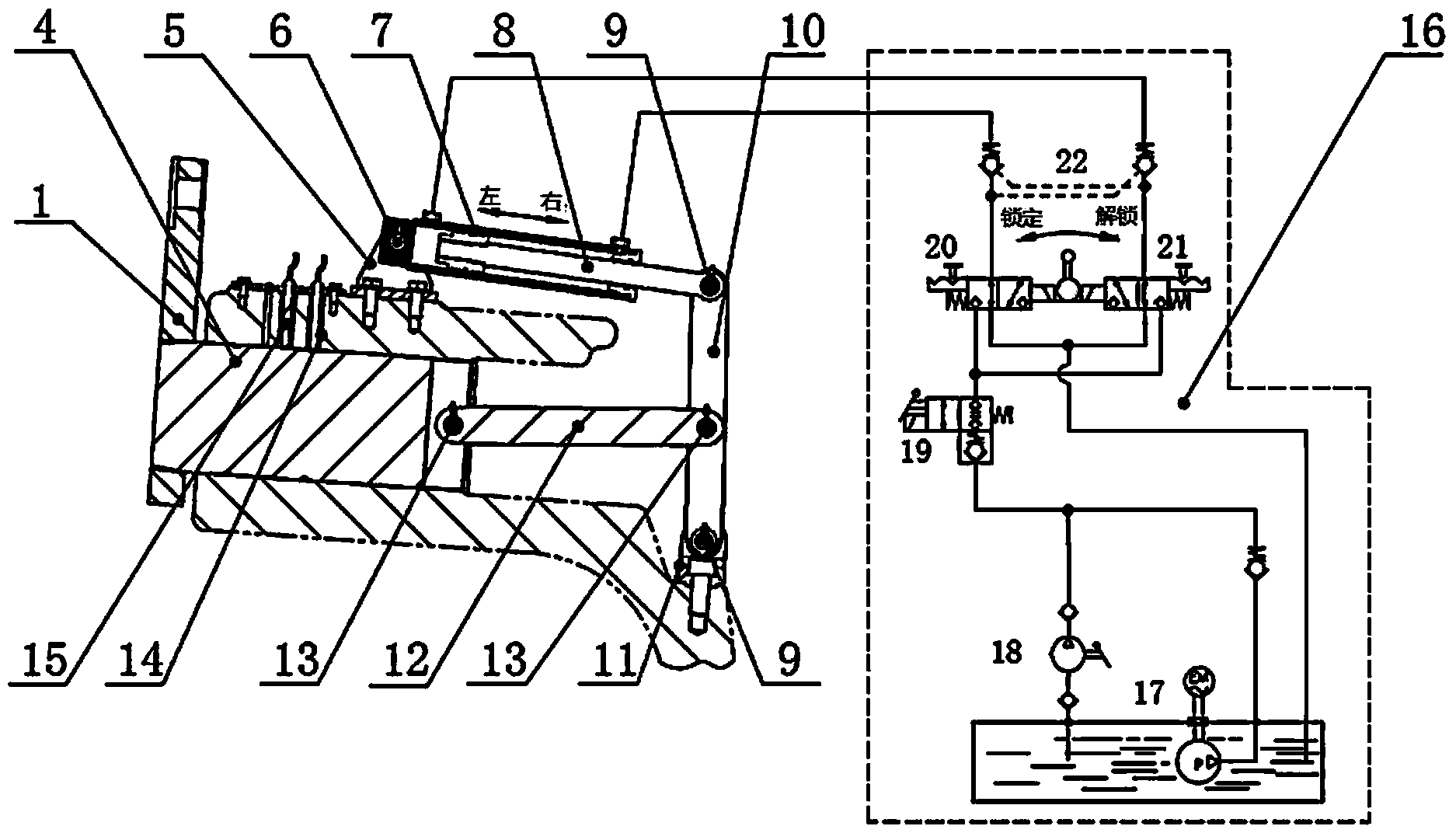
[0020] Such as figure 1 As shown, this embodiment involves: wind wheel 0, wind wheel locking disc 1, rotational speed positioning sensor 2, wind wheel locking mechanism 3, control unit 29, wherein: the wind wheel is locked 0 is the locking object, and the wind wheel locking disc 1 Rotation speed positioning sensor connected to wind wheel 0 2 Determine the position of the wind wheel through optical signals, the control unit 11 outputs a drive signal according to the optical signal, drives the wind wheel to rotate to the position that needs to be locked, and the control unit 29 sends out a wind wheel alignment signal , Drive the actuator wind wheel locking mechanism 11 to realize the purpose of locking the wind wheel.

[0021] The said wind wheel locking mechanism 3 includes: wind wheel locking pin 4, hydraulic cylinder support 5, first cylindrical pin 6, hydraulic cylinder 7, cylinder connecting rod 8, second cylindrical pin 9, rotating rod 10, rotating rod support The seat 11, th...


PUM


Abstract

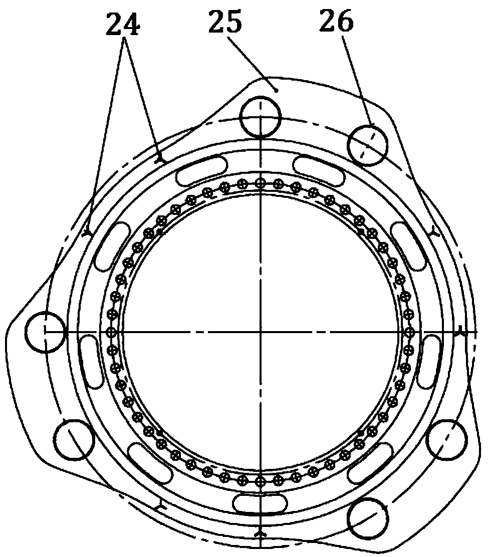
The invention provides a wind wheel locking device of a megawatt-level wind driven generator, and belongs to the technical field of wind power generation. The wind wheel locking device of the megawatt-level wind driven generator comprises a wind wheel locking mechanism, a displacement sensing mechanism and a control unit, wherein the displacement sensing mechanism exactly faces the wind wheel locking mechanism, is connected with the control unit and outputs aligning signals, and the control unit is connected with the wind wheel locking mechanism and outputs driving electrical levels according to the aligning signals to drive a main shaft to rotate to achieve the centering and the starting of the wind wheel locking mechanism. According to the wind wheel locking device of the megawatt-level wind driven generator, through the modification of a wind wheel locking disc, the area of the main shaft entering a manhole of a hub is enlarged, and thus corresponding weight and cost are reduced; due to the three-section type layout of the wind wheel locking disc, the matching positions of the wind wheel locking disc and blades are used for ensuring the effect that a wind wheel is located at a position with the best angle under any locking condition of the wind wheel, and thus the load and torque borne by the system are relatively even; the locking movement of locking pins to the wind wheel locking disc is achieved by using a hydraulic connecting rod mechanism and a main shaft position sensor, and thus the position aligning efficiency of locking holes is improved.

Description

Technical field [0001] The invention relates to a device in the technical field of wind power generation, in particular to a wind wheel locking device of a megawatt-level wind power generator. Background technique [0002] At present, the common impeller locking device of wind turbines uses double locking pins, usually mechanical (using threaded transmission structure), which is troublesome to operate, requires high hole accuracy, requires high operators, and has poor reliability. The single hydraulic lock pin used in some megawatt wind turbines improves the accuracy of the hole alignment and simplifies the operation. However, due to the integral type of the lock pin and the piston, the small vibration load of the wind wheel will cause the lock pin to stay in the lock hole. The vibration displacement of the piston affects the sealing of the piston in the cylinder, and leakage occurs. In addition, the lock pin has a high manufacturing accuracy requirement, a complex structure, and...

Claims


Application Information

Patent Timeline
Patent Type & Authority Applications(China)
IPC IPC(8): F03D11/00
CPCY02E10/722Y02E10/72
Inventor 庄剑余郝胜臣彭飞燕
Owner 上海华仪风能电气有限公司
Learn More