
Portable electric telescopic joint rod

An electric telescopic and portable technology, applied in the direction of electric components, electrical components, electromechanical devices, etc., can solve problems such as unfavorable mass production, processing difficulties, and failures.

Active Publication Date: 2014-03-19
崔鲁彬
View PDF5 Cites 8 Cited by
  • Summary
  • Abstract
  • Description
  • Claims
  • Application Information

AI Technical Summary

Problems solved by technology

[0005] 3. When the lifting rod is upside down and stretches downward, a serious failure will occur
[0006] 4. Structural design is not scientific enough to cause processing difficulties, and it is not conducive to mass production

Method used


Image

  • Portable electric telescopic joint rod
  • Portable electric telescopic joint rod

Examples


Embodiment Construction

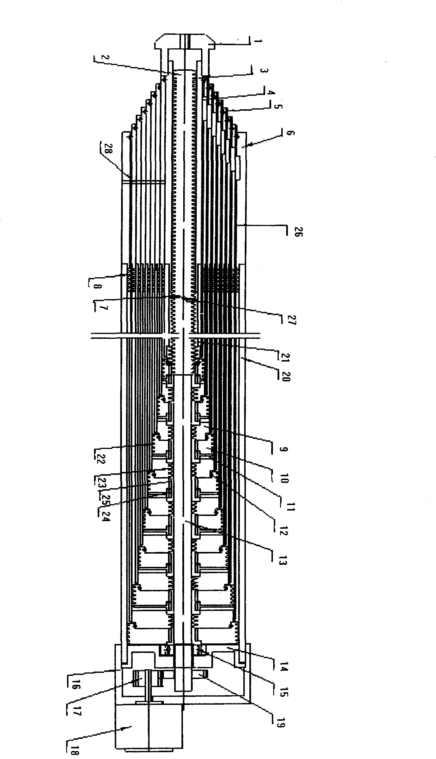
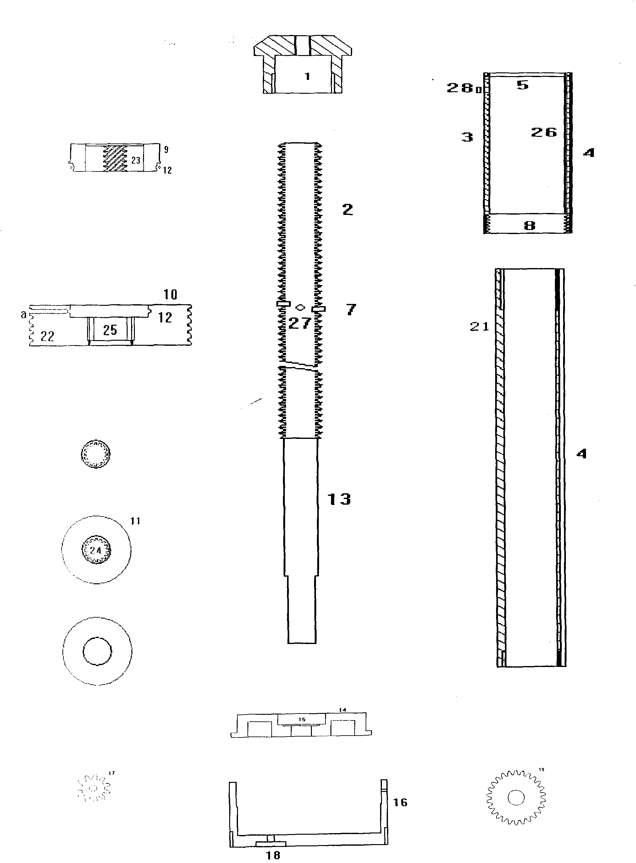
[0018] exist figure 1 and figure 2 In the middle, the motor 18 is fixed under the motor frame 16 with screws, the driving gear 17 pressed on the rotating shaft of the motor 18 meshes with the driven gear 19, and the driven gear 19 is pressed round the bottom end of the polished rod portion 13 of the screw; The lower end of 13 is pressed into the inner hole of the bearing 15, and the outer surface of the bearing 15 is pressed into the circular hole of the fixed frame 14. The lower end of the telescopic joint rod 20 is sleeved into the inner cavity of the motor frame 16; the upper end of the screw rod is the screw rod part 2 and its lower end has a section of the screw rod part 13, and there are two threads on the threaded rib above the screw rod part 2. Two pins 7 protruding 180 degrees from each other, a circular through hole b is drilled in the middle of the two pins 7, and a cylindrical strong magnetic magnet 27 is embedded in the circular through hole; The n circular tel...


PUM


Abstract

Provided is a portable electric telescopic joint rod. The portable electric telescopic joint rod is characterized in that a motor drives a threaded rod to rotate and then sequentially and directly drives n telescopic joint rod bodies, and the portable electric telescopic joint rod can be held by hand to move; when a main nut ascends to the position of a dowel along with the threaded rod, the dowel can pass through a groove in the main nut, a reverse-threaded screw can be clamped when passing through the dowel, and then the threaded rod can drive the reverse-threaded screw to be screwed into a reverse-threaded nut on a telescopic sleeve rod on the outer side; then, a shock absorber is screwed down and sucked on the dowel to prevent shake; with the main nut continuing ascending until the main nut is screwed out of the threaded rod, the reverse-threaded screw below, the telescopic joint rod body on the outer side and the telescopic sleeve rod can ascend perpendicularly, and the main nut below the telescopic joint rod body on the outer side can be lifted to a lead screw portion from a polished rod portion; at the moment, the main nut can continue ascending, and when the main nut ascends to the position below the shock absorber rotating along with the threaded rod, the shock absorber can be screwed into the threads above the main nut and continue ascending along with the main nut. The portable electric telescopic joint rod is simple in structure and can be used for producing portable erecting type or lifting type tools or equipment.

Description

technical field [0001] The invention relates to a portable electric telescopic joint rod, in particular: a portable electric telescopic joint rod that can be directly driven by a motor to rotate n round tube-type telescopic joint rods in turn, and can be held by people to telescopically move in all directions. Electric telescopic rod. Background technique [0002] At present, all kinds of electric lifting rods cannot adapt to the characteristics of allowing people to hold and move in all directions due to the limitations of their internal structures, and have the following shortcomings. [0003] 1. It has serious limitations on its own weight and outer diameter. [0004] 2. After using a thinner or extra-long screw for driving, the screw will vibrate when it performs horizontal telescopic movement. [0005] 3. Serious failure will occur when the lift rod is upside down and retracted downward. [0006] 4. The unscientific structural design causes processing difficulties an...

Claims


Application Information

Patent Timeline
Patent Type & Authority Applications(China)
IPC IPC(8): F16H37/12H02K7/116
CPCF16H37/02H02K7/116
Inventor 崔鲁彬
Owner 崔鲁彬
Learn More