
Zigbee-based equipment monitoring system and its monitoring method

A technology for equipment monitoring and equipment, which is applied in the general control system, control/regulation system, transmission system, etc., can solve the problems of equipment users' loss and inability to monitor and maintain equipment in real time, so as to save wiring costs, improve equipment maintenance efficiency, The effect of saving equipment maintenance costs

Active Publication Date: 2017-12-05
EAST CHINA UNIV OF SCI & TECH
View PDF4 Cites 0 Cited by
  • Summary
  • Abstract
  • Description
  • Claims
  • Application Information

AI Technical Summary

Problems solved by technology

After the equipment is put into production, the equipment in use cannot form further information remote interaction with the equipment manufacturer and maintenance party, and the equipment manufacturer and maintenance party cannot perform online real-time monitoring and professional maintenance on the equipment
The result of this is that the equipment user notifies the equipment manufacturer and maintenance party to maintain the equipment only after the equipment fails and the production stops, which causes great losses to the equipment user.
At the same time, for some special equipment, after the initial installation is completed, the user is often not allowed to move the equipment without authorization.

Method used


Image

  • Zigbee-based equipment monitoring system and its monitoring method
  • Zigbee-based equipment monitoring system and its monitoring method
  • Zigbee-based equipment monitoring system and its monitoring method

Examples


Embodiment 1

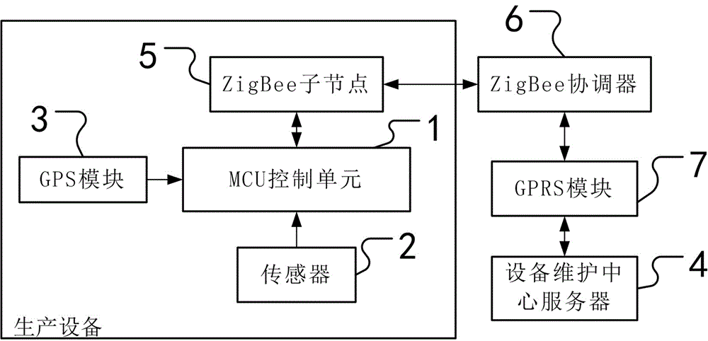
[0052] Embodiment 1: as figure 1 As shown, a ZigBee-based equipment monitoring system, which includes

[0053] The mechanical parts of the equipment, the mechanical parts of the equipment are the mechanical mechanisms for the equipment to complete the production tasks; and the following parts of the monitoring system.

[0054]An MCU control unit 1, the MCU control unit 1 is set on the device. The MCU control unit 1 is used to control the running state of the device and to process data information. The control unit MCU can control various operating parameters of the equipment, control the operation of the equipment, and collect data from various sensors 2, collect GPS data, perform data processing, etc.; and can realize data communication with ZigBee sub-nodes 5 .

[0055] At least one sensor 2 is provided on the device; the sensor 2 is connected to the MCU control unit 1 . The sensor 2 is used to collect and transmit the operating parameter information of the equipment in v...

Embodiment 2

[0071] Example 2, such as Figure 5 , Figure 6 Shown, a kind of monitoring method of the equipment monitoring system based on ZigBee, it comprises the following steps.

[0072] S1: When the equipment is transported, load the equipment on the vehicle.

[0073] S2: The GPS module 3 collects the real-time location information of the device every set time interval, and transmits the real-time location information to the device maintenance center server 4 through the ZigBee module.

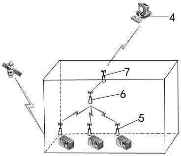
[0074] Specifically: a ZigBee coordinator 6 and a GPRS module 7 are installed in the truck compartment, the ZigBee coordinator 6 communicates with the ZigBee child node 5 on the device during transportation, and the GPS module 3 obtains relevant location information and passes the location information through the ZigBee module Pass it to the server 4 of the equipment maintenance center. The GPRS module 7 is responsible for uploading the data collected by the ZigBee coordinator 6 through the GPRS ne...


PUM


Abstract

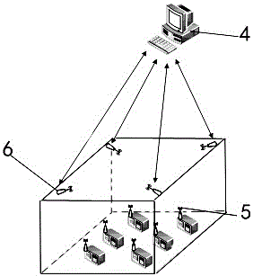
The invention discloses a ZigBee-based equipment monitoring system which comprises an MCU arranged on equipment, a sensor, a GPS module, a ZigBee module and an equipment maintenance center server, wherein the ZigBee module comprises at least one ZigBee child node and at least three ZigBee coordinators; the sensor, the GPS module and the ZigBee child node are arranged on the equipment and are connected with the MCU; and the ZigBee coordinators are mounted at predetermined places in the external environment of the equipment. The invention further discloses a monitoring method of the ZigBee-based equipment monitoring system. According to the ZigBee-based equipment monitoring system and the monitoring method thereof, the safety of the equipment during a transportation process, and the safety in use of the equipment can be ensured, the equipment real-time monitoring and alarming function is realized, the equipment maintenance efficiency is improved, and the equipment maintenance cost is saved.

Description

technical field [0001] The invention relates to the field of equipment monitoring, in particular to a ZigBee-based equipment monitoring system and a monitoring method thereof. Background technique [0002] During the transportation and use of existing industrial equipment, after the initial installation of the equipment, it is often unilaterally supervised and used by the user of the equipment. After the equipment is put into production, the equipment in use cannot form further information remote interaction with the equipment manufacturer and maintenance party, and the equipment manufacturer and maintenance party cannot perform online real-time monitoring and professional maintenance on the equipment. The result of this is that the equipment user notifies the equipment manufacturer and maintenance party to maintain the equipment only after the equipment fails and the production stops, which causes great losses to the equipment user. At the same time, for some special equip...

Claims


Application Information

Patent Timeline
Patent Type & Authority Patents(China)
IPC IPC(8): H04L29/06G05B19/048H04W84/18
CPCG05B19/4185H04L41/04H04W84/18
Inventor 易建军朱晓民徐飞翔龙德罗伟
Owner EAST CHINA UNIV OF SCI & TECH
Learn More