Heating oil tank with interlayer

A technology of oil pool and interlayer, which is applied in the direction of protecting pipelines, heat exchange equipment, and heat preservation through heat insulation, which can solve the problems of easy burns of employees and serious heat loss, etc., and achieve shortened oiling time, reduced oil fume, and reduced energy consumption Effect

Inactive Publication Date: 2014-03-19
HANGZHOU ZIQIANG CHAIN DRIVE
View PDF10 Cites 0 Cited by
  • Summary
  • Abstract
  • Description
  • Claims
  • Application Information

AI Technical Summary

Problems solved by technology

Because there is no heat insulation layer on the surface of the entire oil pool, the temperature is very high, and employees are easily burned. The six 5kw heating pipes are always in a heating state, and the heat loss is very serious.

Method used


Image

  • Heating oil tank with interlayer
  • Heating oil tank with interlayer

Examples


Embodiment 1

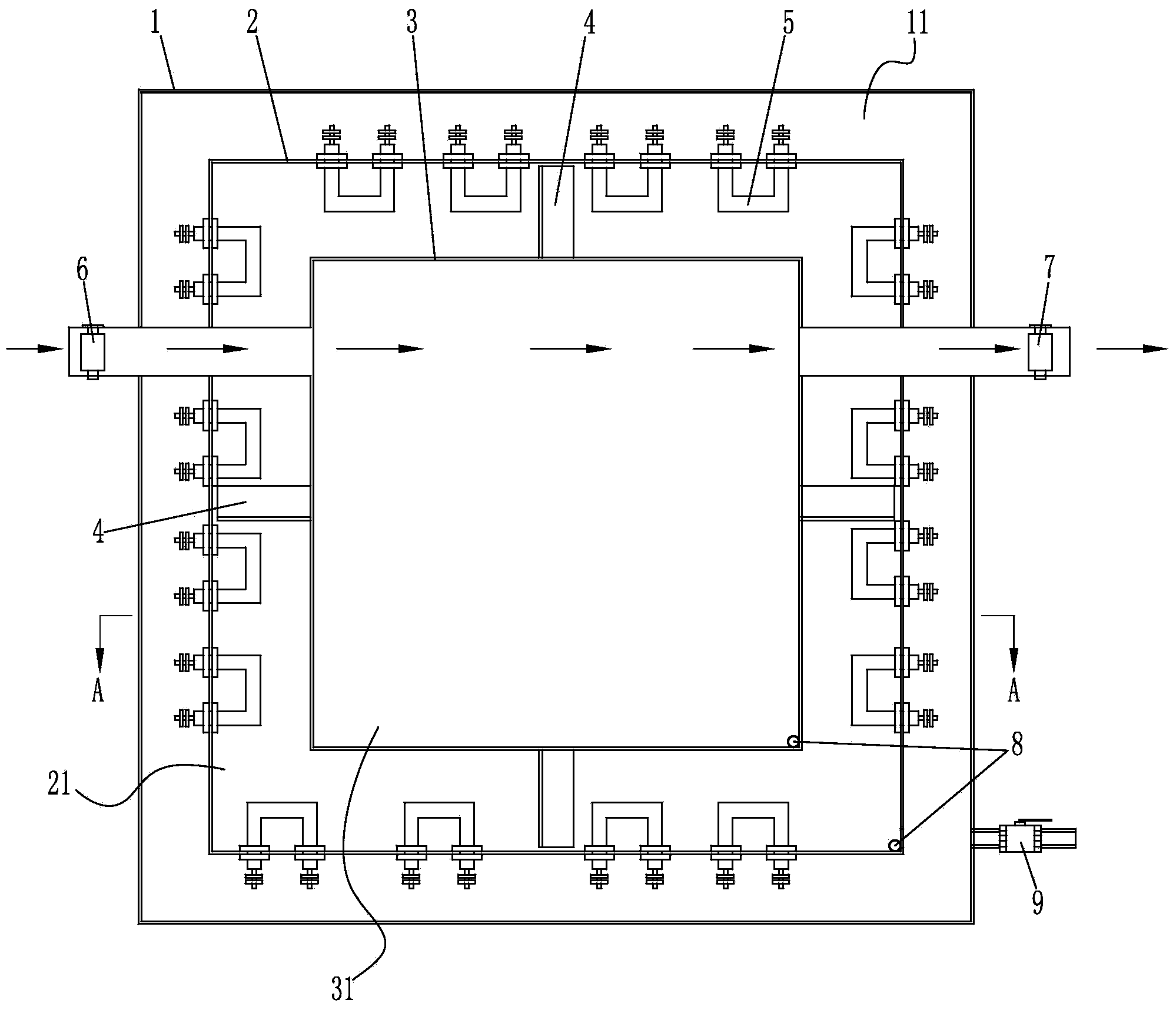
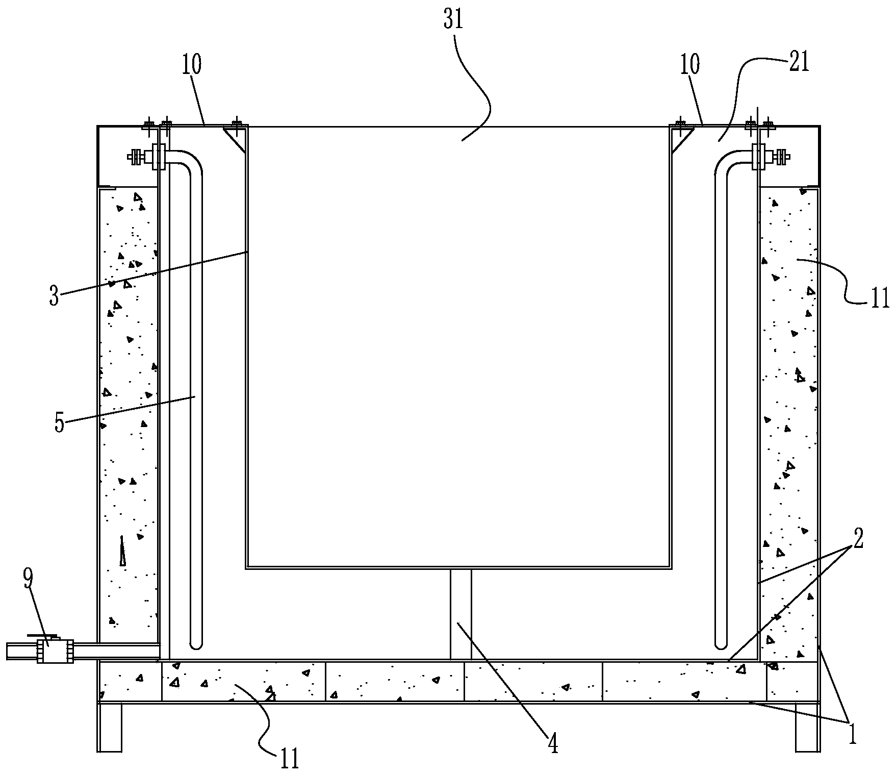
[0011] Such as figure 1 , figure 2 The shown heating oil pool with interlayer includes an outer pool body and an inner pool body 3, the outer pool body includes an outer pool outer wall 1 and an outer pool inner wall 2, and a thermal insulation material 11 is filled between the outer pool outer wall 1 and the outer pool inner wall 2 In the outer pool body, the inner pool body 3 is erected in the air through the bracket 4, and a heat transfer oil cavity 21 for pouring heating oil is formed between the outer pool body and the inner pool body 3, and the heat transfer oil cavity 21 surrounds the surrounding and bottom of the inner pool body 3, and the outer pool body A plurality of heating pipes 5 are installed around the inner wall 2, and the joints of the heating pipes 5 are installed on the upper part of the inner wall 2 of the outer pool. 10. The cover plate 10 is fixedly connected with the outer pool body and the inner pool body 3 to close the heat transfer oil chamber 21. ...


PUM


Abstract

The invention discloses a heating oil tank with an interlayer. The heating oil tank comprises an outer tank body and an inner tank body, a heat-insulation material is packed between the outer wall and the inner wall of the outer tank body; a heat-conducting-oil chamber for accommodating heating oil is formed between the outer tank body and inner tank body; the heat-conducting-oil chamber surrounds the periphery and the bottom of the inner tank body; a plurality of heating pipes are mounted at the periphery of the inner wall of the outer tank body; the contactors of the heating pipes are mounted at the upper part of the inner wall of the outer tank body; the bodies of the heating pipes extend downwards to the lower part of the heat-conducting-oil chamber; a cover plate is mounted at the top of the heat-conducting-oil chamber and is fixedly connected with the outer tank body and the inner tank body so as to seal the heat-conducting-oil chamber; a chain charge channel and a chain discharge channel are mounted at the tops of the outer tank body and the heat-conducting-oil chamber. According to the technical scheme, the heating oil tank is divided into the inner layer and the outer layer; the outer layer is made from a good heat-insulation material; high-temperature heat-conducting oil is added to the space between the inner layer and the outer layer and is heated by the heating tubes; then an oil product in the inner oil tank is heated according to the heat transfer principle.

Description

technical field [0001] The invention belongs to the field of chain manufacturing, in particular to an interlayer heating oil pool for lubricating chains. Background technique [0002] After the chain is assembled, it needs to be oiled and lubricated. Generally, the chain is immersed in an oil pool full of heated and melted lubricating grease for a certain period of time. In the prior art, the heating oil pool used in the oiling workshop is formed by welding steel plates, and the heating pipe is used to directly heat the oil used. The oil pool does not have any heat insulation and heat preservation measures, and the oil temperature rises very slowly. It takes more than 60 minutes to heat a basket of 300kg chain to reach the oil temperature required by the process. Because there is no heat insulation layer on the surface of the entire oil pool, the temperature is very high, and employees are easily burned. The six 5kw heating pipes are always in a heating state, and the heat ...

Claims


Application Information

Patent Timeline
Patent Type & Authority Applications(China)
IPC IPC(8): F16N39/04F16L59/00B21L19/00
Inventor 郎剑胡志华宣碧华
Owner HANGZHOU ZIQIANG CHAIN DRIVE
Why Eureka
Try Eureka