
A gas micro flow measuring device

A measuring device and micro-flow technology, which is applied in measuring devices, liquid/fluid solid measurement, flow/mass flow measurement, etc., can solve problems such as difficulty in measuring small pressure changes, difficulties in measuring small volume changes, and immature understanding of flow mechanisms , to achieve the effect of convenient data picking, improved resolution and accuracy, and stable pressure control

Active Publication Date: 2017-01-18
NORTHEASTERN UNIV LIAONING
View PDF6 Cites 0 Cited by
  • Summary
  • Abstract
  • Description
  • Claims
  • Application Information

AI Technical Summary

Problems solved by technology

[0002] At present, the manufacturing and application of MEMS has become the frontier of high-tech development. Some scales in this field have entered the category of nanotechnology. The flow of gas in micro-nano machinery can enter the slip flow area or even the transition area. Due to the influence of rarefaction and compression effects, its dynamics and thermodynamic properties are very different from those of conventional flow. Although a lot of work has been done on the micro-scale flow characteristics, the understanding of its flow mechanism is far from mature. Some studies The conclusions have not yet been unified. Therefore, it is necessary to develop a measurement device for micro-flow gas flow, no matter from the research point of view or based on the detection of micro-nano devices in the industrial field.
[0003] Theoretically, for a complete gas, the mass flow rate of the time-varying system is determined by the volume, pressure, and temperature changes. If the temperature is controlled to be approximately constant during the measurement process and its influence is ignored, the measurement of a small mass flow rate can be transformed into the measurement of a constant volume. Pressure change or volume change under constant pressure, due to the influence of air leakage and the poor accuracy and real-time performance of indirect pressure measurement under low pressure, it is difficult to measure small pressure changes, and it is also difficult to measure small volume changes under constant pressure

Method used


Image

  • A gas micro flow measuring device
  • A gas micro flow measuring device
  • A gas micro flow measuring device

Examples


Embodiment Construction

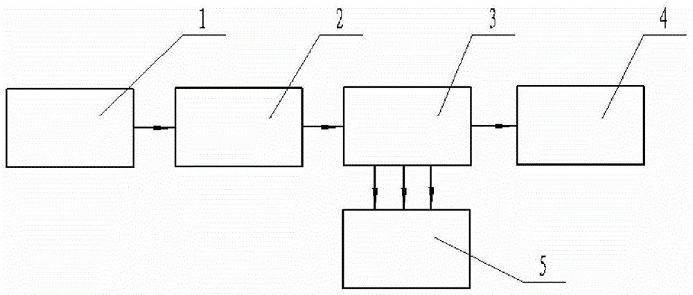
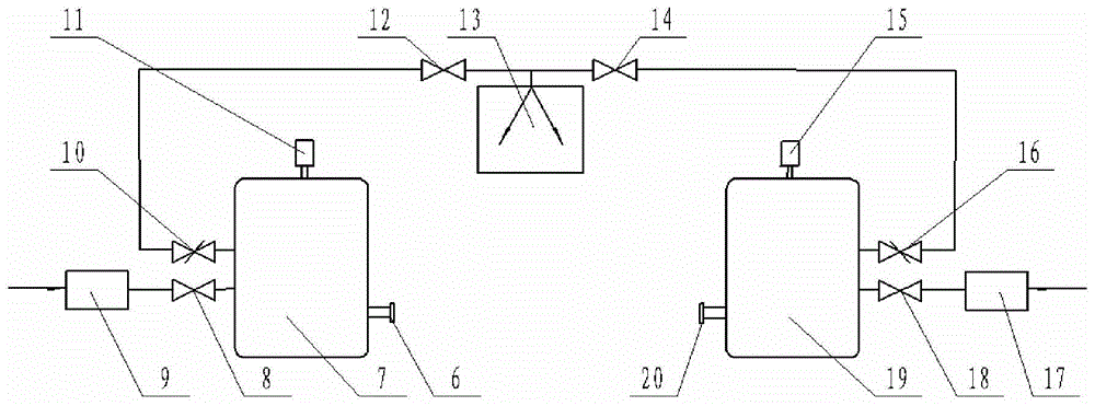
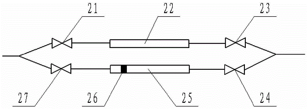
[0014] Such as figure 1 A gas micro-flow measurement device is shown, including an inlet stabilizing container 1, a micro-nano channel or device 2 to be tested, a dual-channel volume indicating unit 3, an outlet stabilizing system 4, a vacuum pumping system 13 and an image recording unit 5 , wherein the inlet voltage stabilizing system 1 is tested micro-nano channel or device 2, the dual-channel volume indicating unit 3, and the outlet voltage stabilizing container 4 are sequentially connected in series to form a closed gas flow space; figure 2 As shown, the inlet pressure stabilizing system 1 includes connecting the first valve 8 and the inlet container 7 sequentially through a conduit, and one port of the inlet container 7 is connected to the first throttle valve 10, the The three valves 12 are fixedly connected to the first pressure sensor 11 and the inlet container interface 6 respectively to the inlet container 7; the outlet pressure stabilizing system 4 includes using a...


PUM


Abstract

The invention discloses a gas micro-flow measuring device. The device comprises an inlet pressure-stabilizing container, a to-be-measured micro-nano channel or device, a two-channel volume indication unit, an outlet pressure-stabilizing container and an image type position recording unit, wherein the pressure in the pressure-stabilizing containers is matched with a gas supply flowmeter through throttle valves for continuous high-resolution regulation; then one channel of the two-channel volume indication unit is used for building stable flow in the to-be-measured micro-nano channel or device with the inlet pressure-stabilizing container and the outlet pressure-stabilizing container; and the other channel for presetting liquid drops is switched on, and the image type position recording unit consisting of a microscope objective and a CCD (charge coupled device) camera is used for tracking the movement of the liquid drops. The measuring device has the advantages of high measuring accuracy and resolution and proneness to implementation.

Description

technical field [0001] The invention relates to a measurement device, which belongs to the field of measurement technology, in particular to a gas micro-flow measurement device, which is used for experimental measurement of gas flow in micro-nano-scale channels or components. Background technique [0002] At present, the manufacturing and application of MEMS has become the frontier of high-tech development. Some scales in this field have entered the category of nanotechnology. The flow of gas in micro-nano machinery can enter the slip flow area or even the transition area. Due to the influence of rarefaction and compression effects, its dynamics and thermodynamic properties are very different from those of conventional flow. Although a lot of work has been done on the micro-scale flow characteristics, the understanding of its flow mechanism is far from mature. Some studies The conclusions have not yet been unified. Therefore, it is necessary to develop a measurement device f...

Claims


Application Information

Patent Timeline
Patent Type & Authority Patents(China)
IPC IPC(8): G01F1/66
Inventor 岳向吉巴德纯巴要帅刘坤
Owner NORTHEASTERN UNIV LIAONING
Learn More