Light source device and liquid crystal display device

A technology of a light source device and a light source unit, which is applied in the direction of light sources, electric light sources, point light sources, etc., can solve problems such as uneven brightness, and achieve the effect of reducing the number and expanding the gap interval

Inactive Publication Date: 2016-02-24
SHARP KK
View PDF9 Cites 0 Cited by
  • Summary
  • Abstract
  • Description
  • Claims
  • Application Information

AI Technical Summary

Problems solved by technology

[0003] Patent Document 1 adopts a method of suppressing streak-like brightness unevenness. In a direct-type LED backlight, the shadows generated by the pillar portion of the optical lens and its adhesive resin blocking the light from the light-emitting element overlap each other. overlap, which causes the above-mentioned uneven brightness in the form of ribs, but the light diffusion lenses used are all the same

Method used


Image

  • Light source device and liquid crystal display device
  • Light source device and liquid crystal display device
  • Light source device and liquid crystal display device

Examples


Embodiment approach 1

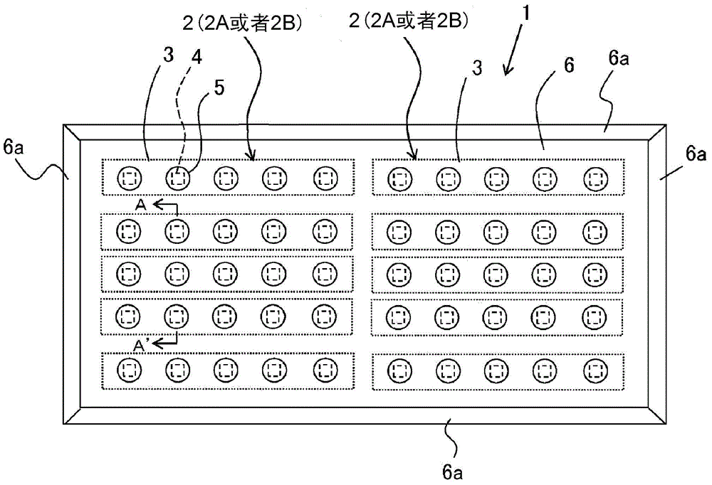
[0079] figure 1 It is a plan view schematically showing an example of the arrangement of LED modules of the LED light source device in Embodiment 1 of the present invention.

[0080] exist figure 1 Among them, the LED light source device 1 of Embodiment 1 is composed of a plurality of LED modules 2, and usually has multiple rows, but here, for convenience, five rows are arranged in the lateral direction, and each row is arranged with two rectangular modules on the left and right. In addition, among the rectangular LED modules 2 of 5 rows in the horizontal direction, in order to improve the brightness of the central part of the screen, although not explicitly shown here, the rectangular LED modules 2 of 3 rows in the center are arranged so that The longitudinal arrangement gaps are tight, and the LEDs 4 on the central side are relatively close.

[0081] Each LED module 2 has a printed wiring board surface 3, and a plurality (here, five) of LEDs 4 connected in series mounted...

Embodiment approach 2

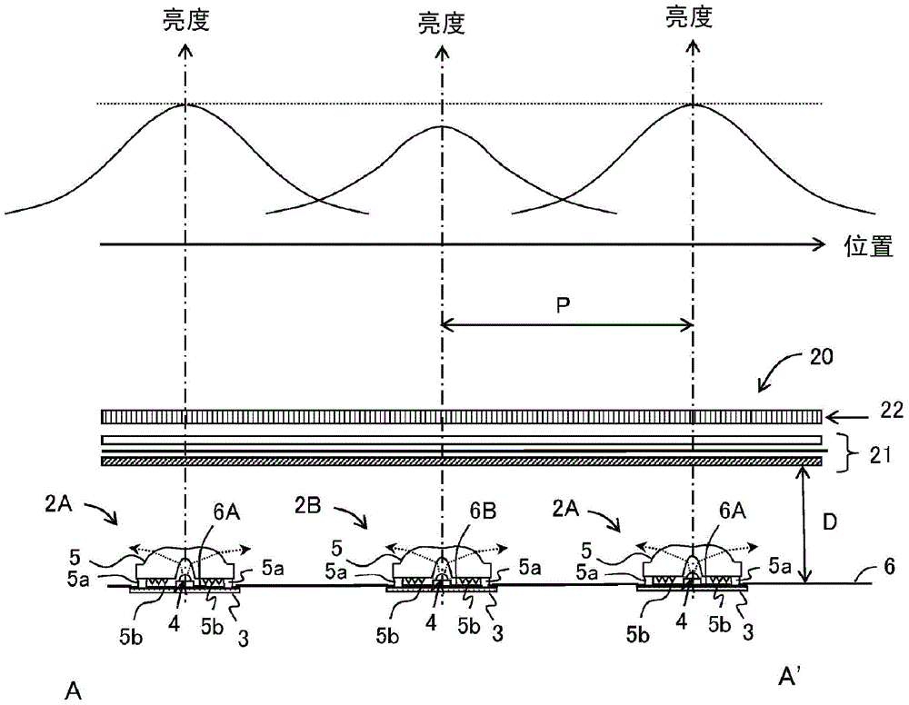
[0104] In the first embodiment described above, the case where a plurality of light source units are arranged in a matrix form in the row direction and the column direction in plan view is described, and luminance peaks are alternately arranged for each row and each column. A light source unit with a high contrast ratio between light and dark and a light source unit with a low peak brightness and a small contrast difference between light and dark are described. In the case of a high light source unit with a narrow light distribution angle (light directivity) and a light source unit with a low luminance peak and a wide light distribution angle (light directivity).

[0105] That is, compared with the case of the first embodiment described above, the point of difference is that in the first embodiment described above, the light source unit with a high luminance peak value and a large contrast difference between light and dark and the light source unit with a low peak luminance val...


PUM

PropertyMeasurementUnit
reflectanceaaaaaaaaaa

Abstract

The purpose of the present invention is to suppress uneven brightness of the surface light source to improve the display quality of the surface light source. In the present invention, one or more LED modules (2A) with one or more light source parts with higher peak brightness and larger contrast difference between light and dark and one or more LED modules with lower peak brightness and smaller contrast difference between light and dark are arranged alternately. An LED module (2B) of a light source part. The one or more light source parts have a white resist (6A, 6B) as a reflective sheet provided on the substrate area around the LED (4) (the substrate area directly below the light diffusion lens (5), The difference in reflectance of the white resists (6A, 6B) is used to form a light source section with a high peak luminance and a large contrast difference between light and dark, and a light source section with a low peak luminance and a small contrast difference between light and dark. Thus, the difference in reflectivity of the white resist (6A, 6B) is consciously used to adjust and control the brightness distribution (contrast between light and dark) from the light diffusion lens (5), so that the bright part (8) and the dark part (7 ) to cancel each other out to greatly suppress the brightness unevenness.

Description

technical field [0001] The present invention relates to a light source device using a plurality of LED modules, etc., and a liquid crystal display device using the light source device as a backlight, wherein a plurality of light emitting diodes (LEDs) are mounted in the LED module as a light source unit. Background technique [0002] Such a conventional liquid crystal display device includes a transmissive liquid crystal panel, and a backlight is provided behind the transmissive liquid crystal panel. Conventionally, CCFL (Cold Cathode Fluorescent Lamp) has been the mainstream of light source devices used as backlights. However, with the advancement of LED technology in recent years, LEDs are expected to be used instead of CCFLs as light sources. [0003] Patent Document 1 adopts a method of suppressing streak-like brightness unevenness. In a direct-type LED backlight, the shadows generated by the pillar portion of the optical lens and its adhesive resin blocking the light fr...

Claims


Application Information

Patent Timeline
Patent Type & Authority Patents(China)
IPC IPC(8): G02F1/13357F21S2/00F21Y101/02
CPCF21V13/04F21K9/60F21V7/24G02F1/133603G02F1/133606G02F1/133611
Inventor 高濑干竹村英夫
Owner SHARP KK
Why Eureka
Try Eureka