
Improved Angle Adjustment Mechanism for Endoscope

An angle adjustment, endoscope technology, applied in endoscopy, application, medical science and other directions, can solve the problems of high manufacturing precision, soft tissue damage, human tissue perforation, etc., to reduce labor intensity, facilitate processing and assembly, prevent damage effect

Active Publication Date: 2016-08-17
YOUCARE TECH CO LTD
View PDF3 Cites 0 Cited by
  • Summary
  • Abstract
  • Description
  • Claims
  • Application Information

AI Technical Summary

Problems solved by technology

Due to operation errors caused by long-term operation fatigue of the operator, it is likely that when the soft endoscope intervenes in the human body, a large extrusion force will occur between the soft endoscope lens and the human tissue. When the extrusion force exceeds a certain When the threshold is exceeded, it will lead to soft tissue damage, which may lead to medical accidents such as perforation of human tissue
At present, there are roughly two types of flexible endoscopes, one is to use an angle slider to limit the position, and the other is to use a traction device with a locking mechanism. These two types of endoscopes have complex structures and require high manufacturing precision. The assembly of various parts requires high correlation and interaction, and a high degree of dependence on other devices of the endoscope. The operation requires the coordination and adjustment of the endoscope as a whole, and the use efficiency of the endoscope is low.

Method used


Image

  • Improved Angle Adjustment Mechanism for Endoscope
  • Improved Angle Adjustment Mechanism for Endoscope
  • Improved Angle Adjustment Mechanism for Endoscope

Examples


Embodiment Construction

[0016] The present invention will be further described in detail below with reference to the drawings and specific embodiments.

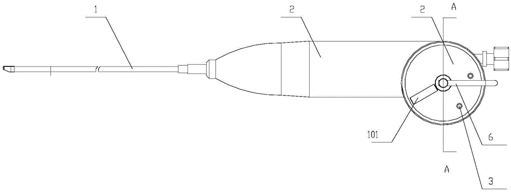
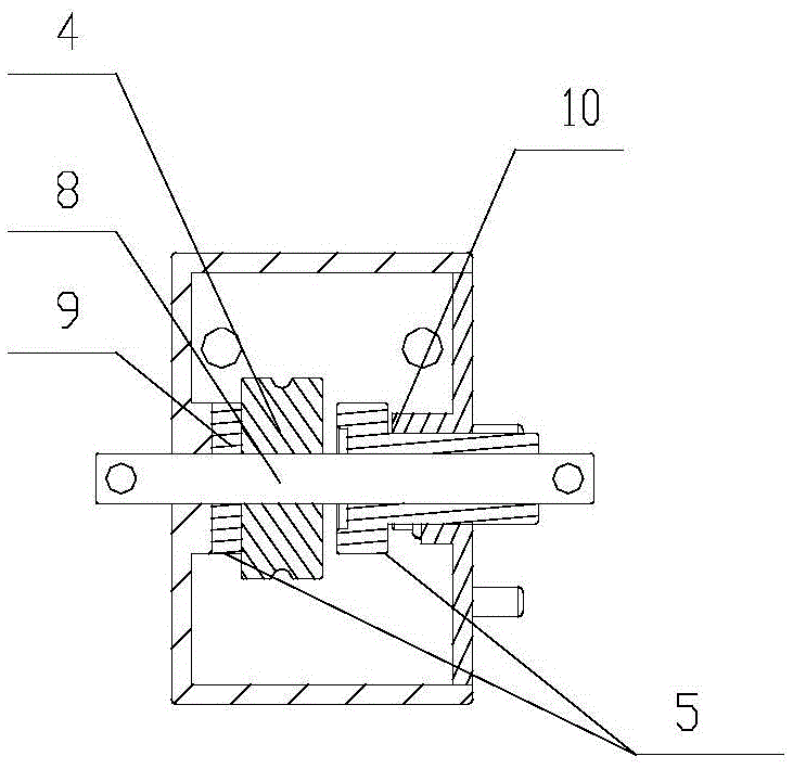
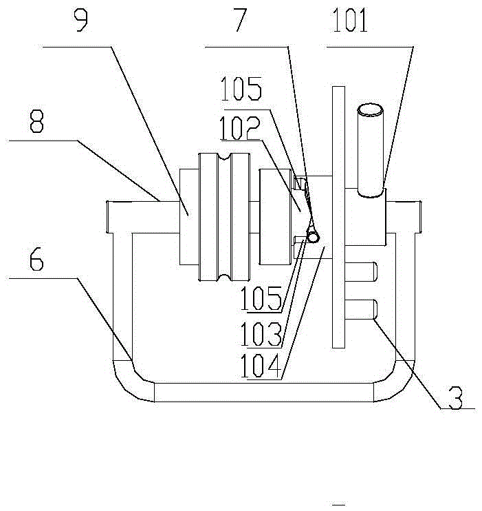
[0017] The improved angle adjustment mechanism for endoscopes as shown in the figure includes an angle adjustment wire, a central shaft 8, a wire rope runner 4 and a locking mechanism 5. One end of the angle adjustment wire is connected with the endoscope soft sheath 1, and the other One end is wound on the wire rope runner 4, which is sleeved on the central shaft 8 and fixedly connected to it. The two ends of the central shaft 8 are located in the positioning holes in the endoscope handle 2 and can rotate in the positioning holes. The shaft 8 is fixedly connected with the angle adjustment handle 6; the locking mechanism 5 includes a fixed friction plate 9 sleeved on the central shaft 8 and fixedly connected to it, and is movably sleeved on the central shaft 8 and can compress the wire rope runner 4 The axial compression mechanism 10 on the fixed frict...


PUM


Abstract

The invention provides an improved angle adjusting mechanism for an endoscope. The improved angle adjusting mechanism for the endoscope comprises an angle adjusting steel wire, a center shaft, a steel wire rope turning wheel and a locking mechanism. One end of the angle adjusting steel wire is connected with a soft sheath of the endoscope, the other end of the angle adjusting steel wire is wound on the steel wire rope turning wheel, the steel wire rope turning wheel is arranged on the center shaft in a sleeved mode and fixedly connected with the center shaft, the two ends of the center shaft are located in locating holes in a handle of the endoscope, and the center shaft is fixedly connected with an angle adjusting handle. The locking mechanism comprises a fixed friction plate which is arranged on the center shaft in a sleeved mode and fixedly connected with the center shaft and an axial pressing mechanism which is movably arranged on the center shaft in a sleeved mode and can press the steel wire rope turning wheel onto the fixed friction plate. The steel wire rope turning wheel is arranged between the fixed friction plate and the axial pressing mechanism. The improved angle adjusting mechanism for the endoscope can meet the requirement of free positioning in the operation process, prevent misoperation from harming a patient, achieve conformance of the bending angle of the angle adjusting handle and the bending angle of the soft sheath, lead the soft sheath to be locked automatically at an operation position, and meet the requirement that an operator can operate the endoscope by one hand.

Description

Technical field [0001] The invention relates to medical equipment, in particular to an improved angle adjustment mechanism for endoscopes. Background technique [0002] In clinical medicine, treatment with endoscope is currently the most commonly used diagnosis and treatment method. This method is the so-called minimally invasive diagnosis and treatment method, which causes less damage to the patient. Traditional soft endoscope treatment requires the cooperation of multiple doctors, and the diagnosis and treatment effect of soft endoscope is highly dependent on the doctor's technique and experience. To avoid repeated angle adjustment and positioning in the patient's body, there are higher requirements for the stability and sensitivity of the flexible endoscope device. The high safety and high efficiency of the endoscopic device is an urgent need to meet the requirements of clinical diagnosis and treatment. Due to operating errors caused by long-term fatigue of the operating phy...

Claims


Application Information

Patent Timeline
Patent Type & Authority Patents(China)
IPC IPC(8): A61B1/005
Inventor 李建兴吴耀辉
Owner YOUCARE TECH CO LTD
Learn More