Breather valve structure

A breathing valve and valve cover technology, which is applied in the direction of respiratory protection devices and life-saving equipment, can solve the problems of insufficient welding fastness between the breathing valve and the respirator or filter mask body, low degree of automatic assembly, and insufficient breathing, and achieve outstanding results. Substantial features, reasonable design structure, easy welding effect

Inactive Publication Date: 2014-03-26
SHANGHAI GANGKAI PURIFYING PRODS
View PDF2 Cites 14 Cited by
  • Summary
  • Abstract
  • Description
  • Claims
  • Application Information

AI Technical Summary

Problems solved by technology

[0004] The structure of the breathing valve used in the existing respirator or filter mask has certain defects, the degree of automatic assembly is low, the exhaust volu

Method used


Image

  • Breather valve structure
  • Breather valve structure
  • Breather valve structure

Examples


Embodiment Construction

[0014] The present invention will be further described below in conjunction with the accompanying drawings and embodiments.

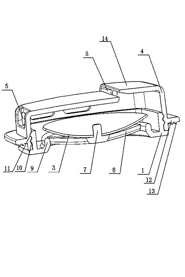
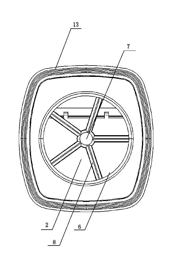
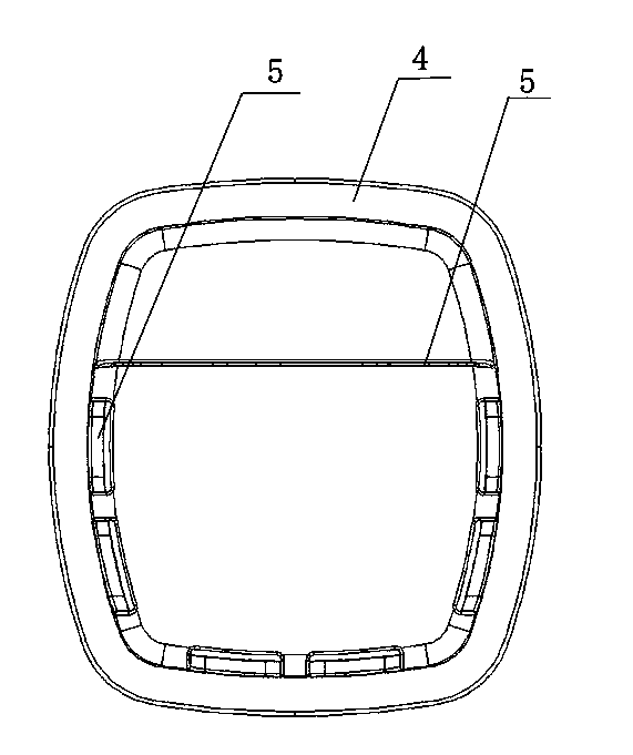
[0015] The invention discloses a breathing valve structure, which includes a base 1, which is different from the prior art in that: the surface of the base 1 is provided with a valve hole 2, and the inside of the valve hole 2 of the base 1 is covered with a diaphragm 3, and the base 1 Connected with the valve cover 4, a hollow cavity is formed between the base 1 and the valve cover 4, and an exhaust port 5 is opened at the valve cover 4.

[0016] During specific implementation, the surface of the base 1 is provided with a circular hole 6, and the center of the circular hole 6 is provided with a diaphragm 3 fixing column 7, and a gap between the diaphragm fixing column 7 and the inner edge of the circular hole 6 There are support bars 8, and the diaphragm fixing column 7 is divergent to the surrounding. There are 3-9 support bars 8, and each support bar ...


PUM


Abstract

The invention relates to a breather valve structure. Valve holes are formed in the surface of a base, membranes cover the inner sides the valve holes of the base, the base is connected with a valve deck, a hollow cavity is formed between the base and the valve deck, and exhaust holes are formed in the valve deck. According to the breather valve structure, a step structure is formed on the surface of the valve deck, and thus automatic assembling and welding on an opening cover on an automatic machine can be carried out conveniently; besides common peripheral exhaust holes, the top exhaust holes are added in the step structure, and thus breathing is smoother; welding lines are added on the edge of the valve deck, welding is easier, and welding firmness is improved; the valve deck and the base are assembled into an integrated structure by using a snap joint mechanism, the overall designed structure of the product is reasonable, full automatic assembling can be achieved, and compared with the prior art, the breather valve structure has outstanding substantive features and remarkable improvement.

Description

technical field [0001] The invention relates to the technical field of protection and purification products, in particular to a breathing valve structure with a top exhaust port, and in particular to its mechanical connection structure. Background technique [0002] Comparative document 1, patent number: CN200610156295.7, patentee: 3M Innovation Co., Ltd., application date: 2002.05.01, this case discloses "a respirator with a one-way valve", which includes: a mask, which having at least one opening for receiving a one-way valve; and a one-way valve comprising: a valve port and a valve seat at least partially surrounding the valve port; and a cantilevered valve flap, the The valve flap has a first portion attached to the outside of the valve port of the respirator and an adjacent second portion freely movable from a first position in which the second portion seals against the valve seat to the second portion A second position spaced apart from the valve seat by at least a po...

Claims


Application Information

Patent Timeline
IPC IPC(8): A62B9/02
Inventor 陈孝兆
Owner SHANGHAI GANGKAI PURIFYING PRODS
Why Eureka
Try Eureka