
Direct injection type air purifier

An air purifier, direct-injection technology, applied in the improvement of air purifiers, in the field of direct-injection air purifiers, can solve the problems of reducing air intake, inconvenient maintenance, complex structure, etc., to improve purification efficiency and improve cleanliness , the effect of increasing the air intake

Inactive Publication Date: 2014-03-26
刘宝林
View PDF5 Cites 30 Cited by
  • Summary
  • Abstract
  • Description
  • Claims
  • Application Information

AI Technical Summary

Problems solved by technology

Since these indoor air purifiers currently use plasma or electronic dust-collecting air purifiers, although they can be made into smaller volumes, they also have a certain effect of purifying the air, but their structures are complex and not easy to maintain. The internal environment is harsh, seriously affecting the life of the purification device, and it is also impossible to adjust the humidity of the indoor space
Spray purifiers are also widely used because of their simple structure. However, in order to ensure that the air entering the device is as clean as possible, the existing spray purifiers usually have a filter at the air inlet. Adding a filter at the air inlet position will greatly reduce the air intake, so that the purification efficiency of the air purifier is not high; if you want to ensure the air intake, generally increase the area of ​​the air inlet, but if the area of ​​the air inlet is too large, it will Affect the appearance of the purifier

Method used


Image

  • Direct injection type air purifier

Examples


Embodiment Construction

[0017] The present invention will be described in further detail below in conjunction with the accompanying drawings and embodiments. Wherein the drawings are only for illustrative purposes and cannot be interpreted as limitations on this patent; in order to better illustrate the following embodiments, some parts of the drawings will be omitted, enlarged or reduced, and do not represent the size of the actual product; for this field For those skilled in the art, it is understandable that some well-known structures and descriptions thereof may be omitted in the drawings.

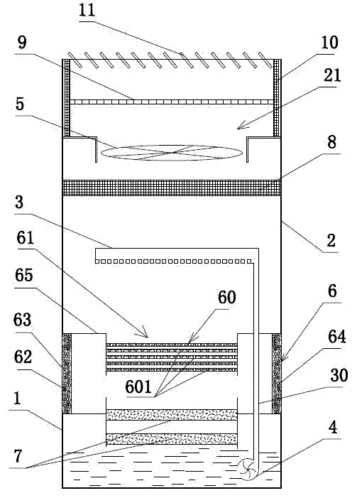
[0018] Direct injection type air purifier structure of the present invention is as attached figure 1 As shown, it includes a water tank 1, a body 2, a shower head 3, a water pump 4, an exhaust fan 5 and a filter cover 6. The body 2 is located above the water tank 1, and the filter cover 6 is arranged between the body 2 and the water tank 1. The filter cover 6 is an annular structure, and the cavity surrounde...


PUM


Abstract

The invention discloses a direct injection type air purifier which comprises a water tank, a machine body, a spray header, a water pump and an exhaust fan. The machine body is positioned above the water tank; an air outlet is formed in the machine body; the exhaust fan is arranged in the air outlet; a water outlet of the water pump is communicated with the spray header; a water inlet of the water pump is communicated with an inner cavity of the water tank; a ring-shaped filtering cover is arranged between the machine body and the water tank; a spray chamber is formed by a cavity surrounded by the filtering cover; the spray header is positioned above the spray chamber; a water curtain sprayed by the spray header can pass through the spray chamber; the upper end of the spray chamber is communicated with the air outlet of the machine body; the lower end of the spray chamber is communicated with the inner cavity of the water tank. The cavity surrounded by the filtering cover is the spray chamber, so that air enters the spray chamber from the surrounding of the filtering cover, the air filtered by the filtering cover is washed by the water curtain sprayed by the spray header to be purified and the purified air is finally exhausted from the air outlet; the air can enter the spray chamber from the surrounding of the filtering cover, so that the supply air rate is increased and the purifying efficiency of the air purifier is improved.

Description

technical field [0001] The invention relates to an air purifier, in particular to a direct-injection air purifier, which belongs to the improvement technology of the air purifier. Background technique [0002] In the space where we live and work, air pollution is everywhere. In order to create a living and working space with good air quality, various air purifiers have entered thousands of households, and now the air purifiers on the market There are many varieties and different structures, such as electrostatic type, electronic dust collection type, plasma type, spray type, etc.; and different types of air purifiers are suitable for different occasions, such as dedicated to household indoors or dedicated to enterprise production Workshops, etc., the use of these different occasions has different air purification effects. For indoor air purifiers, it is often made into a cabinet type, including a body, a built-in purification space with a purification device, and air inlet ...

Claims


Application Information

Patent Timeline
IPC IPC(8): B01D50/00B01D53/18B01D53/02F24F1/00
Inventor 刘宝林
Owner 刘宝林
Learn More