Centrifugal machine capable of controlling material layers

A material layer control and centrifuge technology, applied in the field of centrifuges, can solve problems such as poor control accuracy

Inactive Publication Date: 2014-03-26
连云港双惠机械有限公司
View PDF0 Cites 1 Cited by
  • Summary
  • Abstract
  • Description
  • Claims
  • Application Information

AI Technical Summary

Problems solved by technology

In order to ensure the normal operation of the centrifuge, overload work is not allowed, and the form of operator experience judgment is often used, and the control accuracy is poor.

Method used


Image

  • Centrifugal machine capable of controlling material layers
  • Centrifugal machine capable of controlling material layers

Examples


Embodiment Construction

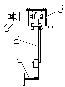
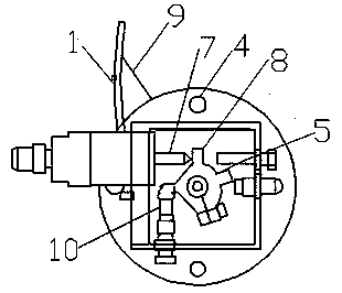
[0011] The present invention is a kind of centrifuge capable of controlling the material layer. The drum of the centrifuge is provided with a blocking plate 1, and the blocking plate 1 is connected with the transmission shaft 2 through the blocking plate arm 9, and the transmission shaft 2 is arranged on In the shaft seat 3; the proximity switch 4 is arranged on the shaft seat 3 of the centrifuge; the transmission sleeve 5 is installed on the transmission shaft 2; the parking cylinder 6 is arranged on the shaft seat 3, the parking cylinder 6 is a piston, and the piston rod of the parking cylinder 6 7 is in contact with the push arm 8 of the drive sleeve 5; a reset device is provided on the shaft seat 3, and the reset device includes a return spring 10 installed on the shaft seat 3 and a reset arm installed on the drive sleeve 5.

[0012] Such as figure 1 , figure 2 As shown, an implementation example of the present invention, the material layer control device, a material blo...


PUM


Abstract

The invention discloses a centrifugal machine capable of controlling material layers. A striker plate is arranged inside a drum of the centrifugal machine and is connected with a transmission shaft through a striker plate arm, and the transmission shaft is arranged inside a shaft base. A proximity switch is arranged on the shaft base of the centrifugal machine. When the centrifugal machine is used and the thickness of materials inside the drum exceeds a certain value, the materials can push the striker plate, the striker plate arm can approach a control switch, a control signal can be output when the distance reaches the preset value, a feeding device stops feeding, overload working can be prevented, and normal working of the centrifugal machine is guaranteed.

Description

technical field [0001] The invention belongs to the field of centrifuges, in particular to a centrifuge capable of material layer control. Background technique [0002] Centrifuges are widely used in chemical industry, petroleum, food, pharmaceutical, mineral processing, coal, water treatment and shipbuilding and other departments. Its role is to separate the solid particles in the suspension from the liquid; or to separate the two different densities in the emulsion and the liquids that are not compatible with each other. The main structure of the centrifuge is: a shock-absorbing base, an organic casing is installed on the shock-absorbing base, a drum is arranged inside the casing, a cover is provided on the top of the casing, many through holes are opened on the side wall of the drum, and the inner wall There is a filter screen on the top, the drum is driven to rotate by the driving device, and a feeding device is installed on the machine cover. When working, the rotating...

Claims


Application Information

Patent Timeline
Patent Type & Authority Applications(China)
IPC IPC(8): B04B11/04
Inventor 刘兴波
Owner 连云港双惠机械有限公司
Why Eureka
Try Eureka