Solder wire structure preventing splashing
A technology of solder wire and flux, applied in welding medium, welding equipment, welding/cutting medium/material, etc., can solve the problems of spatter, single pressure release direction, pressure release, etc.
- Summary
- Abstract
- Description
- Claims
- Application Information
AI Technical Summary
Problems solved by technology
Method used
Image

Examples
Embodiment Construction
[0024] In order to make the above objects, features and advantages of the present invention more comprehensible, specific implementations of the present invention will be described in detail below in conjunction with the accompanying drawings.
[0025] In the following description, many specific details are set forth in order to fully understand the present invention, but the present invention can also be implemented in other ways than those described here, so the present invention is not limited by the specific embodiments disclosed below.
[0026] As mentioned in the background art, since not only the problem of pressure release during the soldering process needs to be solved, but also the phenomenon of spatter caused by a single direction of pressure release needs to be solved, so it is necessary to provide a solder wire structure that prevents spatter.
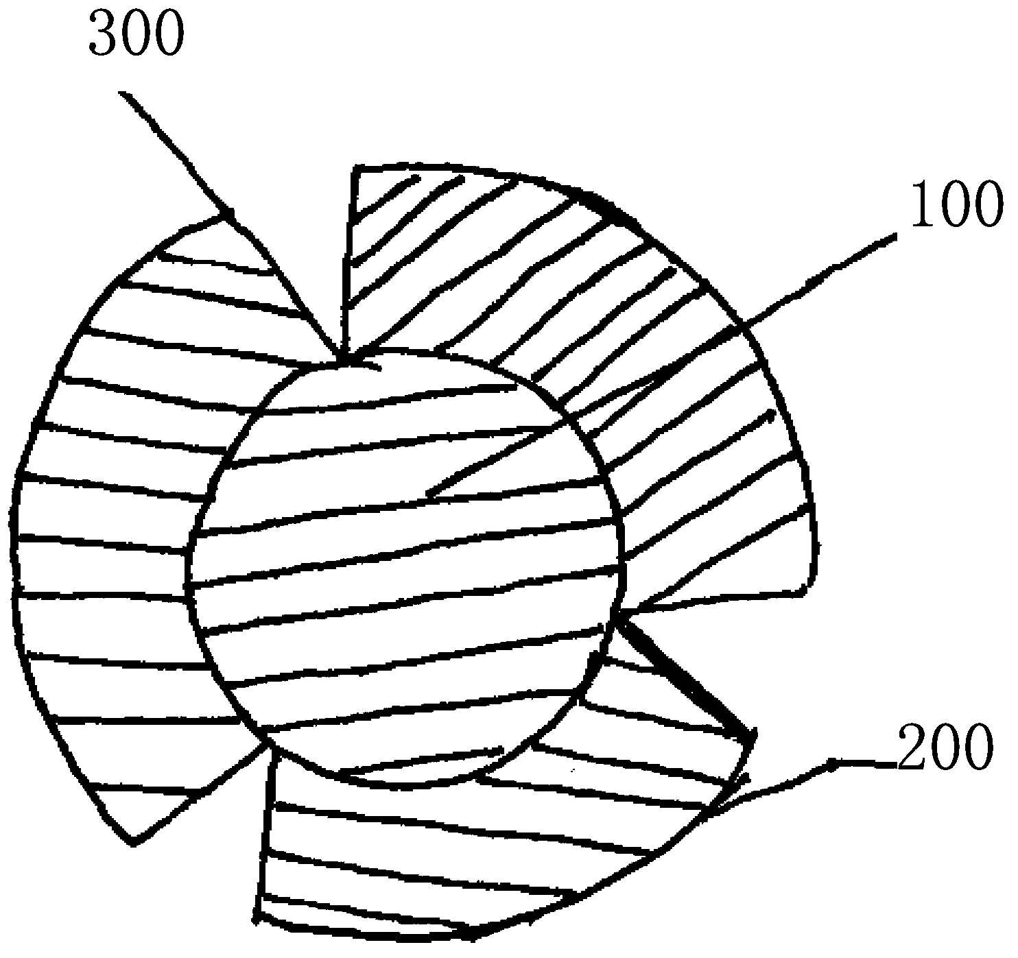
[0027] see Figure 4 , Figure 4 It is a schematic diagram of a preferred embodiment of the anti-spatter solder wire st...
PUM
 Abstract
Description
Claims
Application Information