
Main core nut differential screwing mechanism of drive axle assembly

A drive axle assembly, cone nut technology, applied in metal processing, metal processing equipment, manufacturing tools, etc., to achieve the effect of simple power transmission structure and easy tightening state

Active Publication Date: 2014-03-26
ANHUI JEE AUTOMATION EQUIP CO LTD
View PDF7 Cites 12 Cited by
  • Summary
  • Abstract
  • Description
  • Claims
  • Application Information

AI Technical Summary

Problems solved by technology

Rely on feel and experience to judge the size of tightening and pre-tightening force, which cannot meet the assembly requirements due to the influence of external conditions and human errors

Method used


Image

  • Main core nut differential screwing mechanism of drive axle assembly

Examples


Embodiment Construction

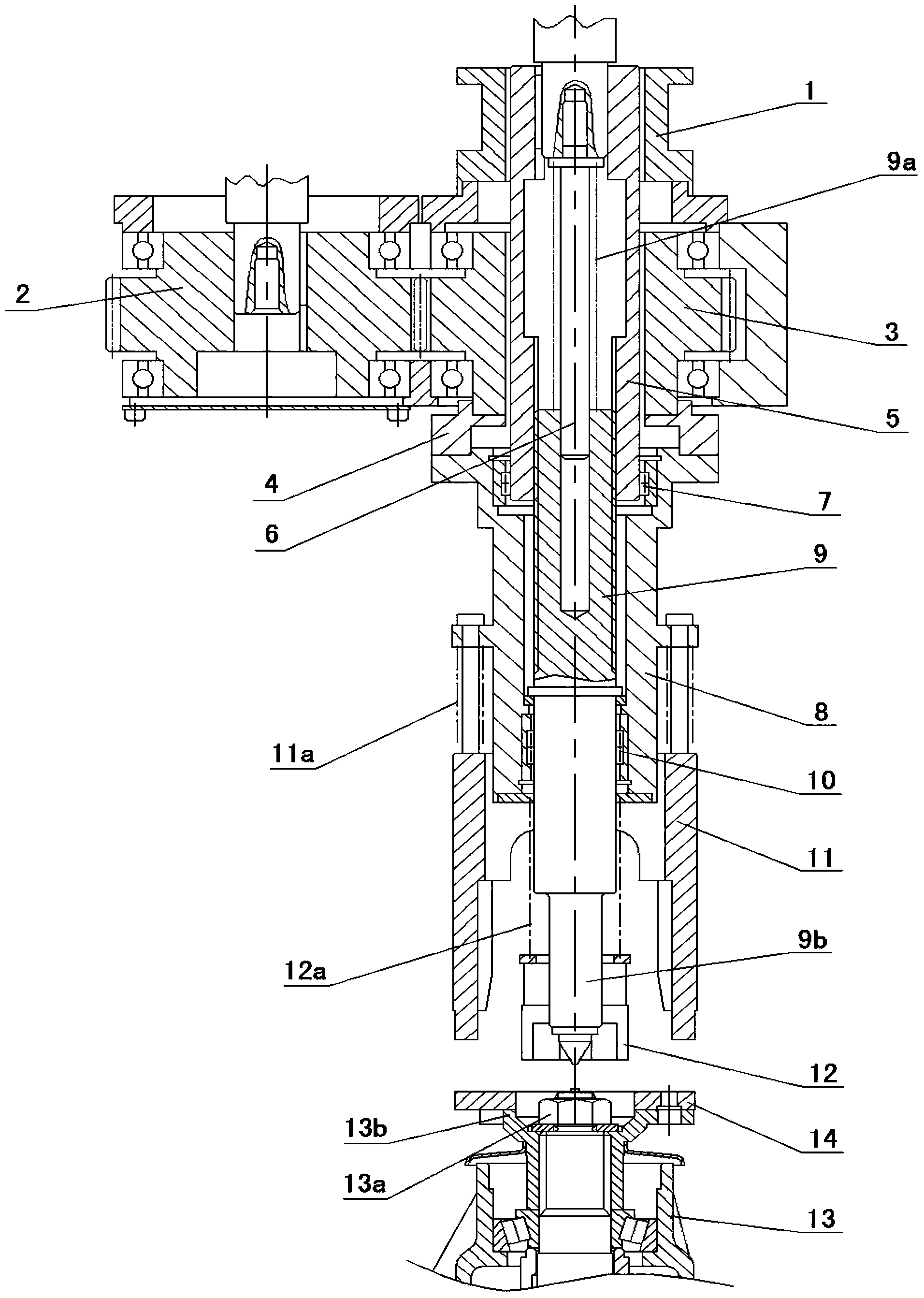
[0020] see figure 1 , in specific implementation, the structure of the differential tightening mechanism of the main cone nut of the drive axle assembly is set as follows:

[0021] The transmission line 1 is set, with the first servo motor as the driving part, which is transmitted to the tightening shaft 9b fixedly connected to the bottom of the spline shaft through the torque sensor 1, the spline sleeve 5 and the spline shaft 9 in sequence, and the bottom of the tightening shaft 9b A sleeve 12 is provided, and the sleeve 12 is used to fit on the main cone lock nut 13a, and the floating sleeve 12 transmits torque to the main cone lock nut 13a for tightening the main cone lock nut 13a.

[0022] The second transmission line is driven by the second servo motor, which is transmitted to the transition flange 4 through the driving gear 2, the passive gear 3 meshing with the driving gear, and the transition flange 4 driven by the passive gear 3. Rotating bushing 8 on the top of the ...


PUM


Abstract

The invention discloses a main core nut differential screwing mechanism of a drive axle assembly. The main core nut differential screwing mechanism of the drive axle assembly is characterized in that a first transmission line is arranged and enables a first servo motor to transmit torque to a main cone locking nut through a torque sensor, a spline hub, a spline shaft and a sleeve in sequence; a second transmission line is arranged and enables a second servo motor to transmit torque to a main cone input flange through a driving gear, a driven gear, a transition flange plate, a rotating shaft sleeve and a rotation-stopping claw in sequence; the arranged sleeve and the arranged rotation-stopping claw rotate at the same differential, so that differential screwing of the main cone nut is achieved. The main core nut differential screwing mechanism of the drive axle assembly can achieve real-time adjustment, save assembly time and improve the assembly efficiency.

Description

technical field [0001] The invention relates to a differential tightening mechanism of a main cone nut of a drive axle assembly, more specifically a main cone nut tightening mechanism applied on an axle main reduction assembly line. Background technique [0002] The traditional tightening of the main cone nut is to use a hydraulic machine to carry out unilateral step-by-step pressing and manual tightening. This tightening method depends entirely on the human feeling to determine the tightening state. Not only is it difficult to make the assembly meet the requirements, but also the assembly efficiency is low; existing The mechanical tightening method is to directly tighten the lock nut. Although the assembly efficiency is improved to a certain extent, the size of the tightening force is not controlled, and there are many problems in the assembly quality. If the tightening force is too large, it may damage the main body. Cone; if it is too small, it will be easy to loosen. Th...

Claims


Application Information

Patent Timeline
IPC IPC(8): B23P19/06
CPCB23P19/06B23P19/065B23P2700/50
Inventor 林巨广杨连华郑大维马金王二威王治宇王鹏
Owner ANHUI JEE AUTOMATION EQUIP CO LTD
Learn More