
Roller lathe center frame

A roll lathe and center frame technology, applied in the field of roll lathe center frames, can solve the problems of increased processing costs, low pass rate, and wear of support claws, and achieve the effect of convenient disassembly and installation

Inactive Publication Date: 2014-03-26
JIANGSU DONGYE ROLL
View PDF0 Cites 0 Cited by
  • Summary
  • Abstract
  • Description
  • Claims
  • Application Information

AI Technical Summary

Problems solved by technology

[0002] In the existing lathes for processing rolls, the supporting claws of the center frame are made of copper and cast iron. When processing rolls, due to the heavy weight of the rolls, the supporting claws are severely worn, causing the center of the roll to move down. The product does not meet the technical requirements and is qualified. The rate is low, and the replacement frequency of the supporting claws is very fast, which increases the processing cost and affects the normal production

Method used


Image

  • Roller lathe center frame

Examples


Embodiment Construction

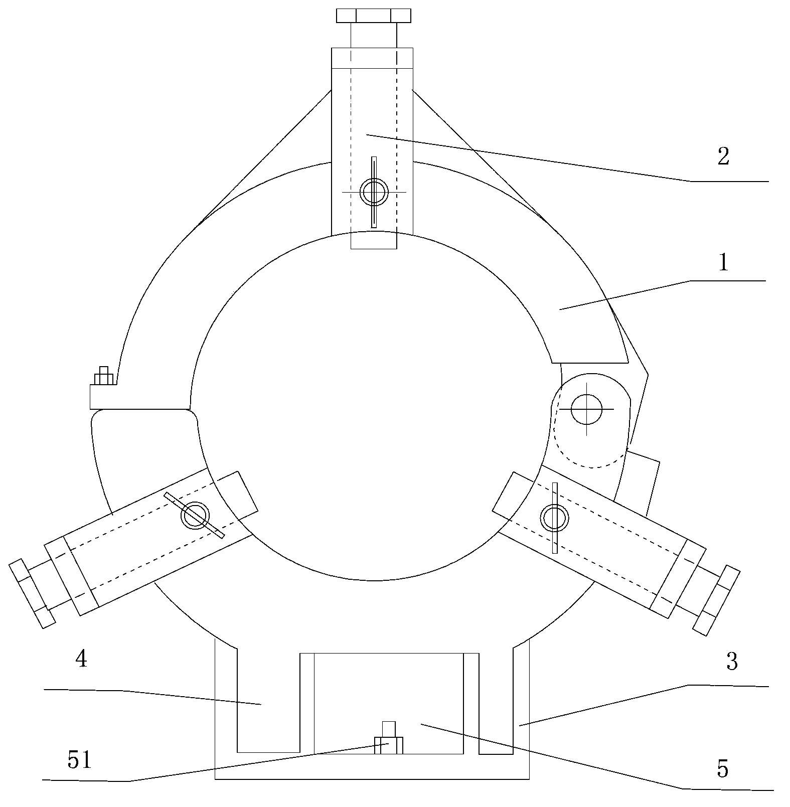
[0010] See figure 1 As shown, a roll lathe center frame includes a ring frame 1, and three radially expandable support rods 2 are arranged on the inner ring of the ring frame 1. It also includes a base 3, and the base 3 and the ring frame 1 The lower end surface is fixedly connected, and the reinforcing rib 4 is fixedly connected between the base 3 and the ring frame 1; the base 3 is provided with a groove 5, and the groove 5 is provided with a bolt 51 for fixing with a lathe.

[0011] The specific embodiments described above have further described the purpose, technical solutions and beneficial effects of the present invention in detail. It should be understood that the above descriptions are only specific embodiments of the present invention and are not intended to limit the present invention. Any modifications, equivalent replacements, improvements, etc. made within the spirit and principles of the present invention shall be included within the protection scope of the prese...


PUM


Abstract

The invention discloses a roller lathe center frame which comprises an annular frame. An inner ring of the annular frame is provided with three supporting rods which are telescopic in the radial direction in a trisection mode. The roller lathe center frame further comprises a base. The base is fixedly connected with the lower end face of the annular frame. A reinforcement rib is fixedly connected between the base and the annular frame. By means of a groove of the base and the reinforcement rib of the roller lathe center frame, the load bearing capacity of the base is ensured and meanwhile, the weight of the base is reduced. Meanwhile, the center frame and a lathe can be conveniently detached and installed.

Description

technical field [0001] The invention relates to the technical field of lathe equipment, in particular to a roll lathe center frame. Background technique [0002] In the existing lathes for processing rolls, the supporting claws of the center frame are made of copper and cast iron. When processing rolls, due to the heavy weight of the rolls, the supporting claws are severely worn, causing the center of the roll to move down. The product does not meet the technical requirements and is qualified. The rate is low, and the replacement frequency of the support claw is very fast, which increases the processing cost and affects the normal production. Contents of the invention [0003] The object of the present invention is to solve the above-mentioned existing problems, and to provide a roll lathe center frame which is convenient for placing rolls and has good wear resistance of support claws. [0004] The purpose of the present invention is achieved in the following manner: a ro...

Claims


Application Information

Patent Timeline
IPC IPC(8): B23Q1/76
CPCB23Q1/766
Inventor 戴建方
Owner JIANGSU DONGYE ROLL
Learn More