Lathe main shaft protruding edge circular disc speed changing device

A speed change device and machine tool spindle technology, which is applied in the direction of drive devices, metal processing machinery parts, metal processing equipment, etc., and can solve problems such as the need to adjust the output speed of the spindle

Inactive Publication Date: 2014-03-26
重庆信奇建材机械制造有限公司
View PDF0 Cites 0 Cited by
  • Summary
  • Abstract
  • Description
  • Claims
  • Application Information

AI Technical Summary

Problems solved by technology

[0004] The present invention intends to provide a machine tool spindle convex edge disc speed change

Method used


Image

  • Lathe main shaft protruding edge circular disc speed changing device

Examples


Embodiment Construction

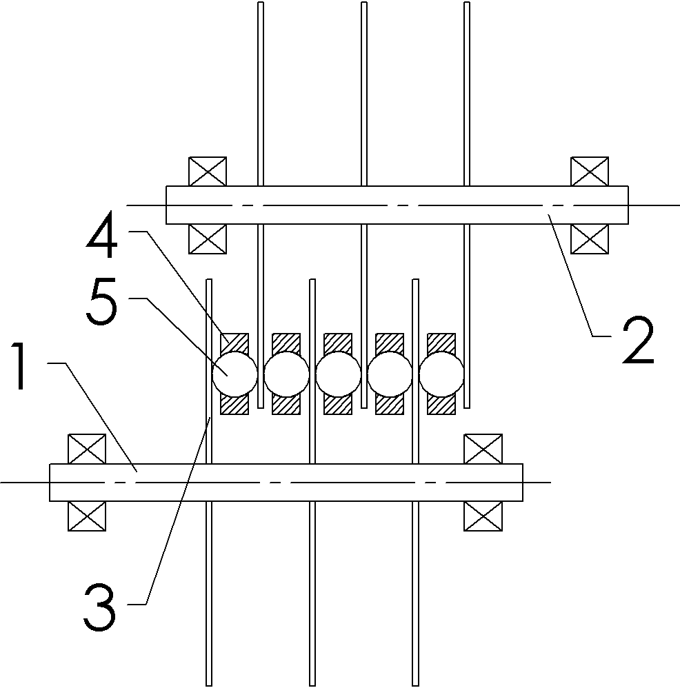
[0010] The reference numerals in the drawings of the description include: input shaft 1 , adjustment shaft 2 , driving conical disk 21 , output shaft 3 , driven flange disk 31 , belt 4 , and spring 5 .

[0011] basically as figure 1 Shown: In this embodiment, including the frame, the input shaft, the adjustment shaft and the output shaft, the input shaft, the adjustment shaft and the output shaft are all horizontally arranged in parallel, and the input shaft is connected with the pulley and the belt with the belt automatic tensioning device. The adjustment shaft is connected. Both the input shaft and the output shaft are connected to the frame through bearings. The adjustment shaft is also equipped with a rotating bearing. The rotating bearing is connected to the frame through a chute. There is also a screw to adjust the horizontal position of the rotating bearing. , to realize the radial horizontal position adjustment of the adjustment shaft. On the adjustment shaft and the ...


PUM


Abstract

The invention discloses a lathe main shaft protruding edge circular disc speed changing device. The problem that in the prior art, main shaft output speed needs to be adjusted is solved. The lathe main shaft protruding edge circular disc speed changing device comprises a machine frame, an input shaft, an adjusting shaft and an output shaft. The input shaft, the adjusting shaft and the output shaft are parallel to each other. The input shaft is connected with the adjusting shaft through a self-tightening belt wheel and a belt. The adjusting shaft can move in the radial direction. More than two driving taper discs and driven protruding edge discs are evenly distributed on the adjusting shaft and the output shaft respectively. The driven protruding edge discs have elasticity along protruding edges. The driving taper discs and the driven protruding edge discs on the adjusting shaft and the output shaft are arranged in an alternating-overlapping mode. The radial distance between the adjusting shaft and the output shaft can be adjusted through the adjusting shaft, parts with different linear speeds on the end faces of the driving taper discs are combined with the protruding edges of the driven protruding edge discs, and finally transmission speed adjusting is achieved. Through the elasticity of the protruding edges, certain thickness changing of the driving taper discs can be borne.

Description

technical field [0001] The invention relates to a mechanical driving device applicable to machine tools. Background technique [0002] A lathe is a machine tool that mainly uses a turning tool to turn a rotating workpiece. Drills, reamers, reamers, taps, dies and knurling tools can also be used for corresponding processing on the lathe. Lathes are mainly used to process shafts, discs, sleeves and other workpieces with rotating surfaces, and are the most widely used machine tools in machinery manufacturing and repair factories. [0003] At present, in the processing of workpieces by lathes, the main shaft is the driving shaft used to provide power. The power brought by its rotation can meet the needs of the various mechanisms of the machine tool, but the requirements for the speed of different mechanisms cannot be completely consistent. How to To satisfy the output speed of the main shaft and meet the requirements of various action mechanisms is a problem that technicians h...

Claims


Application Information

Patent Timeline
IPC IPC(8): B23Q5/12
CPCB23Q5/12B23Q2705/064
Inventor 彭彦
Owner 重庆信奇建材机械制造有限公司
Why Eureka
Try Eureka