
A tractor automatic clutch
An automatic clutch, tractor technology, applied in the direction of control device, transportation and packaging, vehicle parts, etc., can solve the problems of poor working conditions, high labor intensity of the driver, and the driver cannot precisely control the force, so as to reduce labor intensity and facilitate the switching effect
- Summary
- Abstract
- Description
- Claims
- Application Information
AI Technical Summary
Problems solved by technology
Method used
Image

Examples
Embodiment
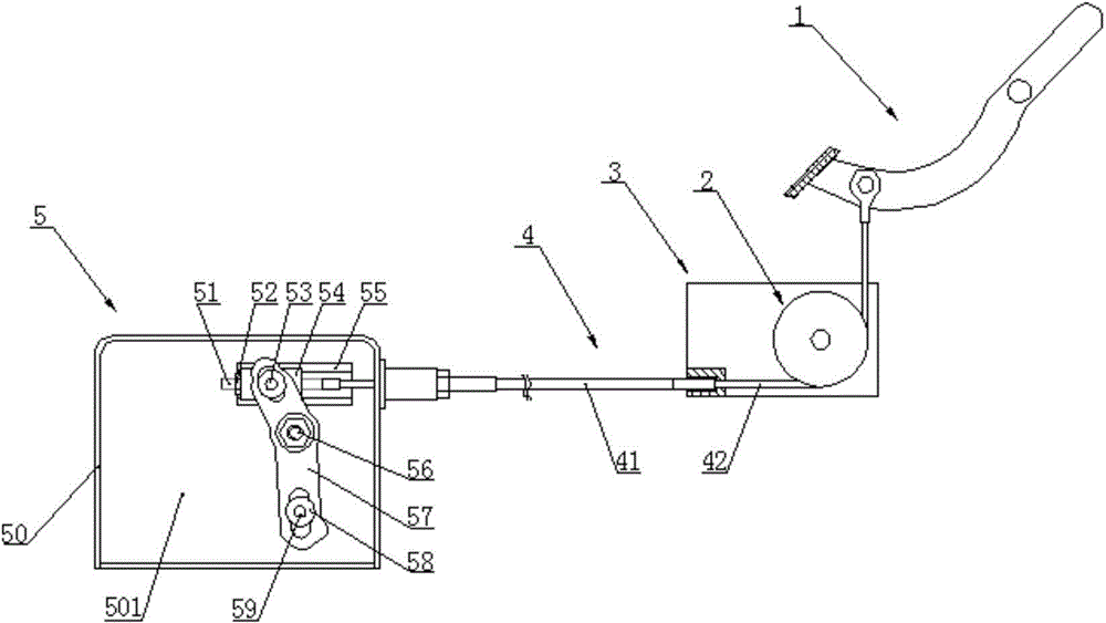
[0034] Such as figure 1 As shown, an automatic clutch for a tractor includes: a clutch pedal 1 , a reversing wheel 2 , a bottom plate 3 , a pull wire 4 and a driving unit 5 .
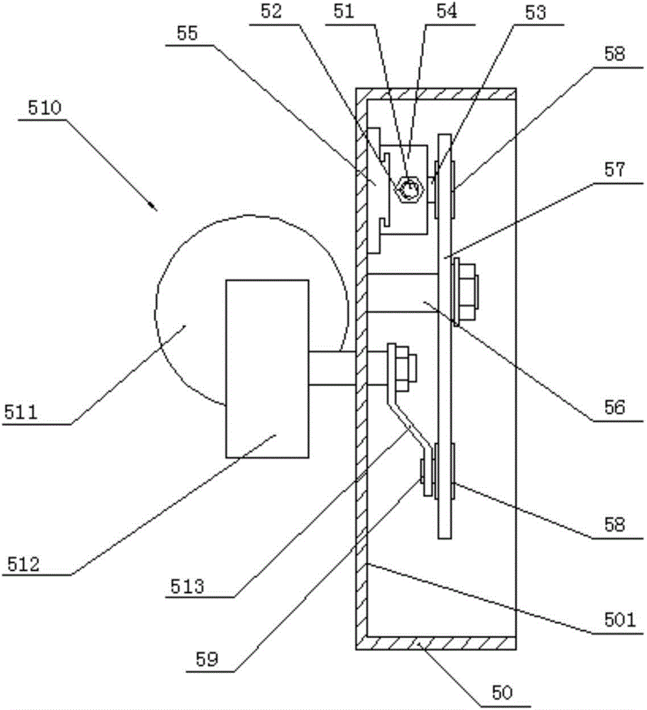
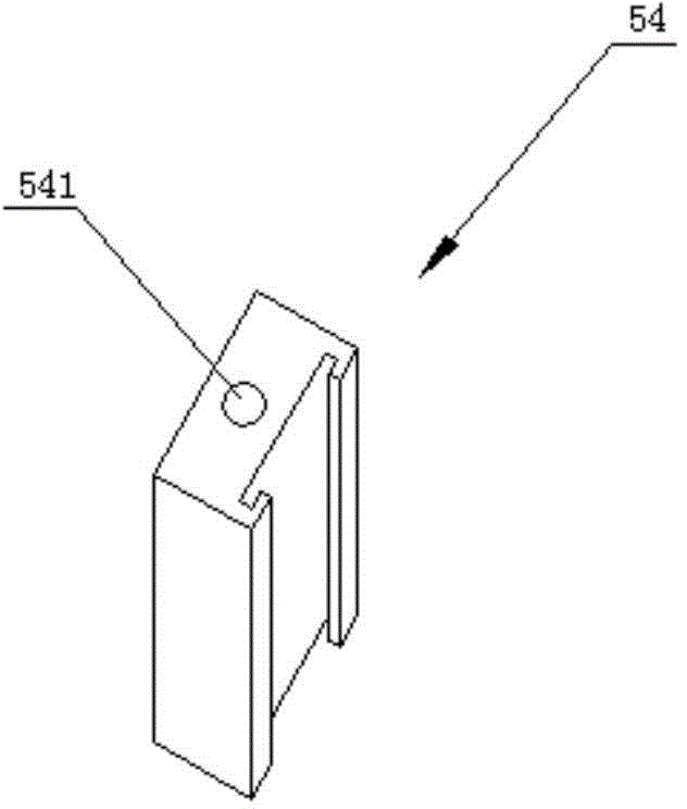
[0035] Such as figure 2 As shown, the driving unit 5 includes a base 50, a guide rail 55, a slide block 54, a first hinge column 53, a second hinge column 56, a third hinge column 59, a swing bar 57, a motor 510 and a roller 58, and the base 50 is fixed. On the corresponding position of the tractor, the guide rail 54 is fixedly arranged on the first surface 501 of the base 50, and the slider 54 is slidably arranged on the guide rail 55, as image 3 As shown, the slider is provided with a through hole 541 along its sliding direction, one end of the first hinged post 53 is fixedly connected with the slider 54, and it is perpendicular to the first surface 501, and one end of the second hinged post 56 is connected to the first surface 501 is fixedly connected, and it is perpendicular to the first surface...
PUM
 Abstract
Description
Claims
Application Information