Vacuum magnetic levitation tunnel

A tunnel and maglev technology, applied in tunnel systems, roads, tracks, etc., can solve problems such as tension, compression, bending deformation, collapse, and incomplete slow release of temperature change stress

Active Publication Date: 2014-03-26
王昕鑫
View PDF11 Cites 2 Cited by
  • Summary
  • Abstract
  • Description
  • Claims
  • Application Information

AI Technical Summary

Problems solved by technology

[0002] Existing vacuum maglev tunnels, such as 00105737, etc., use steel pipes as the tunnel shell, or such as 201120425139, etc., use reinforced concrete as the tunnel shell. When the temperature changes, its length direction will have tension, compression, bending deformation or even fracture due to the different thermal expansion coefficients of the roadbed and tunnel. This is a major safety hazard for high-speed maglev vehicles. 201120425139 does not directly describe how to solve the thermal stress The method should be to use concrete creep to relieve thermal stress by default, but the creep size of concrete is limited by steel bars, and there is a large gap between the thermal expansion coefficient of steel bars and the thermal expansion coefficient of roadbed rock and soil, so roads and bridges must leave Expansion joints, so it seems that the use of reinforced concrete to slow down the temp

Method used


Image

  • Vacuum magnetic levitation tunnel
  • Vacuum magnetic levitation tunnel
  • Vacuum magnetic levitation tunnel

Examples


Embodiment Construction

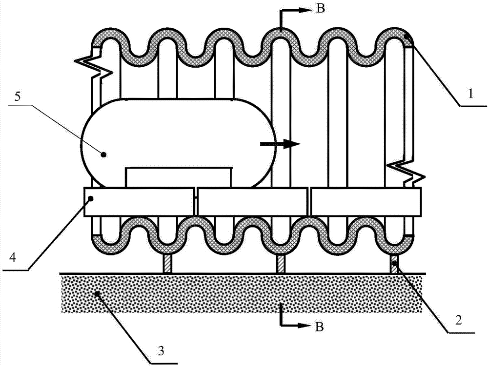
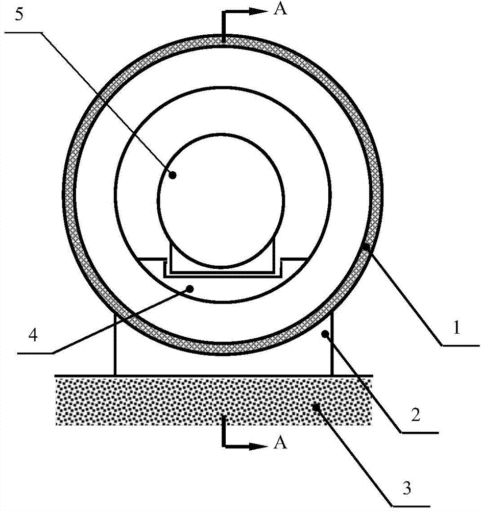
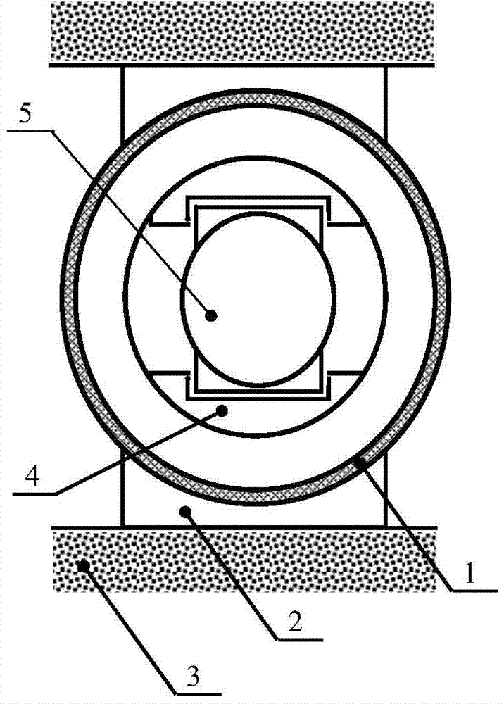
[0012] The present invention includes a tunnel shell 1, a support 2, a roadbed 3, and a magnetic floating block 4 fixed on the tunnel shell 1 to suspend and drive a suspension vehicle 5. It is characterized in that the longitudinal profile of the tunnel shell 1 is a corrugated curved surface, and the transverse profile is a circle. Or ellipse; one end of each magnetic floating block 4 is fixed on the inner side of the bottom of the tunnel shell 1 across the trough of equal wave pitch, and the other end is slidably supported, so that its magnetic buoyancy and magnetic driving force can maintain a uniform temperature change; Install support 2 at the wave crest at the outer side of the bottom of the tunnel shell 1 and the longitudinal fixed position of each magnetic floating block 4, and fix the support 2 on the roadbed 3, so that the longitudinal dimension change between the roadbed and the tunnel shell caused by temperature changes can be evenly distributed. assigned to the elas...


PUM


Abstract

The invention relates to a vacuum magnetic levitation tunnel which comprises a tunnel shell, supports, a roadbed and magnetic levitation blocks for being fixed on the tunnel shell to be suspended and driving a levitation vehicle. The vacuum magnetic levitation tunnel is characterized in that the longitudinal profile of the tunnel shell is a corrugated pipe hook face, and a transverse profile is in a circle or oval shape; one ends of the magnetic levitation blocks are fixed at the positions of the inner side of the bottom of the tunnel shell at equal longitudinally-striding wave pitch number interval, and the other ends of the magnetic levitation blocks are used for sliding supporting; the supports are installed at the positions, at the wave crests equal distance away from the longitudinally-fixing positions of the magnetic levitation blocks, on the outer side of the bottom of the tunnel shell, and the supports are fixed on the roadbed. The buttock line of the corrugated pipe hook face of the tunnel shell is a sine curve and the like. Obviously, fewer materials can be used in the vacuum magnetic levitation tunnel, the longitudinal rigidity of the vacuum magnetic levitation tunnel is reduced to convert the longitudinal internal stress generated by temperature changes into longitudinal elastic deformation, meanwhile, the radial rigidity of the vacuum magnetic levitation tunnel is increased to enable deformation to be not prone to being caused when vacuum and track loads are borne, the temperature change stress is averagely divided by the supports, the uniformity influences of the temperature change stress on magnetic buoyancy and magnetic driving force are reduced, and the components are widely applied to the vacuum magnetic levitation tunnel.

Description

technical field [0001] The invention relates to a vacuum maglev tunnel. Background technique [0002] Existing vacuum maglev tunnels, such as 00105737, etc., use steel pipes as the tunnel shell, or such as 201120425139, etc., use reinforced concrete as the tunnel shell. When the temperature changes, its length direction will have tension, compression, bending deformation or even fracture due to the different thermal expansion coefficients of the roadbed and tunnel. This is a major safety hazard for high-speed maglev vehicles. 201120425139 does not directly describe how to solve the thermal stress The method should be to use concrete creep to relieve thermal stress by default, but the creep size of concrete is limited by steel bars, and there is a large gap between the thermal expansion coefficient of steel bars and the thermal expansion coefficient of roadbed rock and soil, so roads and bridges must leave Expansion joints, so it seems that the use of reinforced concrete to ...

Claims


Application Information

Patent Timeline
IPC IPC(8): B61B13/10
Inventor 金传华王昕鑫梅森王文明郝连红齐亚伦玄璇郑和梅刘志远
Owner 王昕鑫
Why Eureka
Try Eureka