Mine vehicle brake device

A braking device and vehicle technology, applied in the field of braking devices, can solve the problems of low safety and durability, and achieve the effects of simple braking device mechanism, convenient operation, and preventing the mine car from sliding down.

Inactive Publication Date: 2014-03-26
HUAINAN MINING IND GRP
View PDF3 Cites 5 Cited by
  • Summary
  • Abstract
  • Description
  • Claims
  • Application Information

AI Technical Summary

Problems solved by technology

[0003] The existing mine car brake device has the disadvantages of low safety and durability

Method used


Image

  • Mine vehicle brake device

Examples


Embodiment Construction

[0013] The present invention will be further described in detail below in conjunction with the accompanying drawings and specific embodiments.

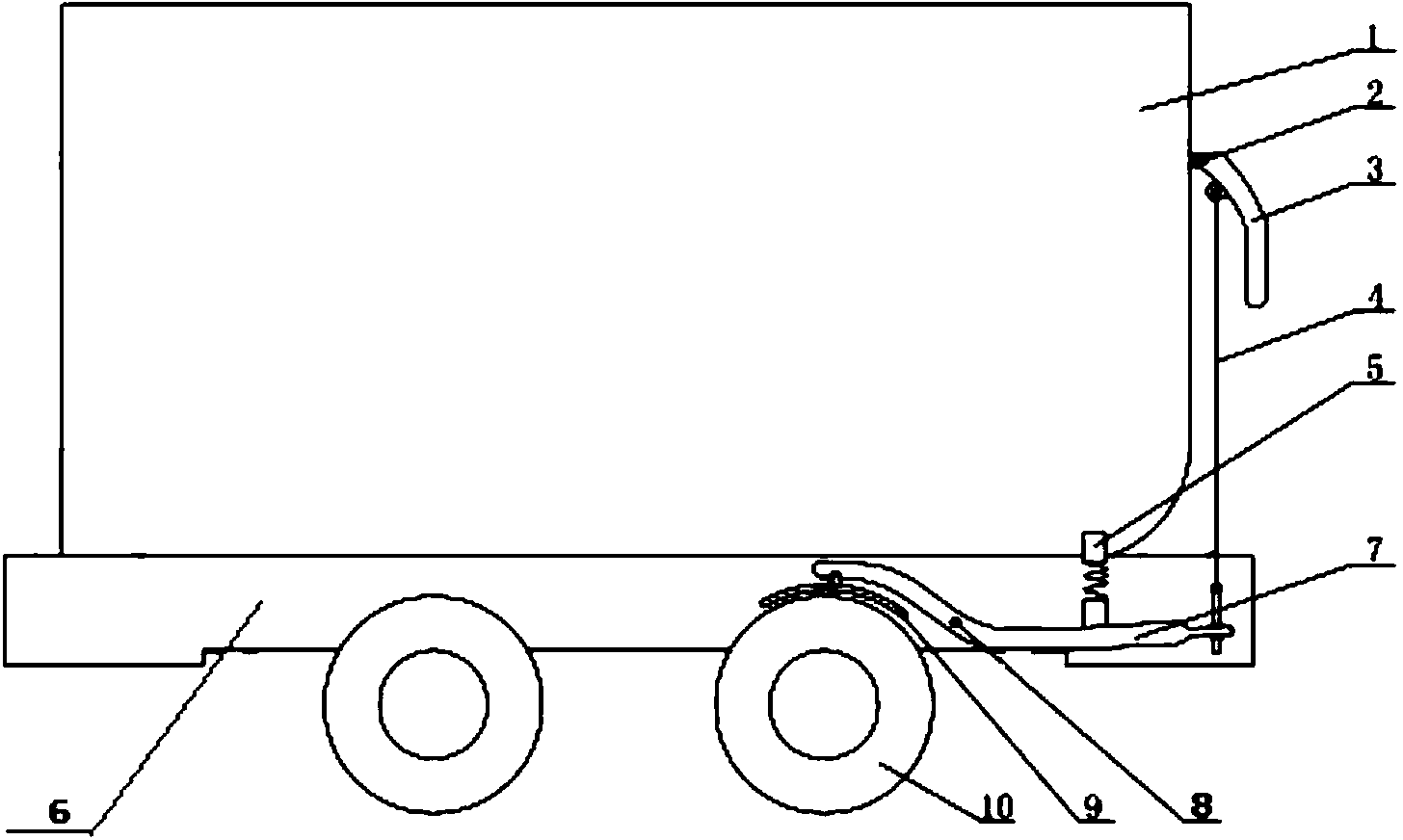
[0014] Such as figure 1 A mining vehicle braking device shown is a mining vehicle braking device, including a car body and wheels 10, a rubber brake block 9 is arranged above the wheel 10, and the rubber brake block 9 is fixed on a transmission rod 7, and the transmission rod 7 passes through the The positioning shaft 8 is connected to the chassis 6 and is connected to the control handle 3 through the wire rope 4. The control handle 3 is connected to the side wall of the carriage 1 through the rotating shaft 2. The transmission rod 7 is located in the chassis 6, between the transmission rod 7 and the carriage 1. A spring device 5 is arranged between them; the rubber brake block 9 is a metal wear-resistant rubber brake block; the spring device 5 includes a spring seat and a return spring, and the return spring is installed in the sprin...


PUM


Abstract

The invention discloses a mine vehicle brake device which comprises a vehicle body and wheels. A rubber brake block is arranged above the wheels, and fixed to a transmission rod, the transmission rod is connected to a chassis through a locating shaft and is connected with a control handle through a steel wire rope, the control handle is connected to the side wall of a vehicle box through a rotating shaft, the transmission rod is arranged in the chassis, and a spring device is arranged between the transmission rod and the vehicle box. The whole mine vehicle brake device is simple in mechanism and convenient to operate, staff simply need to lift the control handle, a mine vehicle can be braked, a mine vehicle sliding accident is prevented, and therefore the function of safety protection can be achieved.

Description

technical field [0001] The invention relates to a braking device, in particular to a mining vehicle braking device. Background technique [0002] Mining cars are narrow-gauge railway vehicles for transporting bulk materials such as coal, ore and waste rocks in mines. Generally, they need to be pulled by locomotives, winches or controlled by staff. However, due to the rugged mine roads, when going uphill or downhill Accidents that mine cars slide down easily occur, which brings potential safety hazards to mine work. Therefore a safe and reliable braking device is very important. [0003] The existing mine car braking device has the disadvantages of low safety and no durability. Contents of the invention [0004] The technical problem to be solved by the present invention is to provide a mining vehicle brake device with simple structure, convenient operation, safety, reliability and long service life. [0005] In order to solve the problems of the technologies described a...

Claims


Application Information

Patent Timeline
Patent Type & Authority Applications(China)
IPC IPC(8): B61H1/00
Inventor 柏云飞
Owner HUAINAN MINING IND GRP
Why Eureka
Try Eureka