

Automatic bar member feeding mechanism
A technology of automatic feeding and parts, which is applied in the direction of conveyor, transportation and packaging, etc., and can solve the problem of uncontrollable rolling speed
- Summary
- Abstract
- Description
- Claims
- Application Information
AI Technical Summary
Problems solved by technology
Method used
Image

Examples
Embodiment Construction
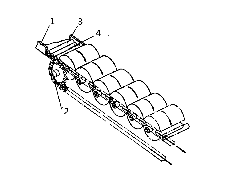
[0011] like figure 1 As shown: it includes the conveying channel 1 for placing bar pieces and the driving sprocket 2 for driving the conveying channel. The conveying channel 1 is inclined towards the direction of the processing station. The conveying channel 1 is composed of a plurality of parallel conveying rods 3. The conveying rod 3 is a slender cylindrical structure, and a groove 4 for placing workpieces is formed between two adjacent conveying rods 3. The width of the groove 4 is greater than the radius of the bar material and smaller than the diameter of the bar material. The length of the conveying rod 3 and the conveying distance Bar stock pieces are the same length.
[0012] When working, use the conveying channel 1 to store the bar material, and form a groove 4 for placing the workpiece between two adjacent conveying rods 3. The width of the groove 4 is greater than the radius of the bar material and smaller than the diameter of the bar material, so that each bar Th...
PUM
 Abstract
Description
Claims
Application Information