Eureka AIR delivers breakthrough ideas for toughest innovation challenges, trusted by R&D personnel around the world.

Cranked link chain

A technology of bending plate chain and chain link, applied in the field of bending plate chain, can solve the problems of production accident, broken chain link, easy falling off of the pin shaft, etc., to increase the service life, reduce the occurrence of accidents, and prevent the pin shaft from moving.

Inactive Publication Date: 2014-03-26
TIANJIN TIANZHONG ZHONGZHI TECH ENG CO LTD
View PDF7 Cites 0 Cited by
  • Summary
  • Abstract
  • Description
  • Claims
  • Application Information

AI Technical Summary

Problems solved by technology

During the use of the bent plate chain, the main reason affecting its life is that when the pin shaft rotates or slightly shifts, the cotter pin at the top of the pin shaft and the side of the chain link will produce friction. Since the cotter pin is relatively thin, it is easy to become a bent plate chain. The weak link of the plate chain, during the operation of the bent plate chain, once the cotter pin breaks, the pin shaft is easy to fall off without restraint, causing the connected chain link to break, which will cause certain production accidents

Method used


Image

  • Cranked link chain
  • Cranked link chain
  • Cranked link chain

Examples


Embodiment Construction

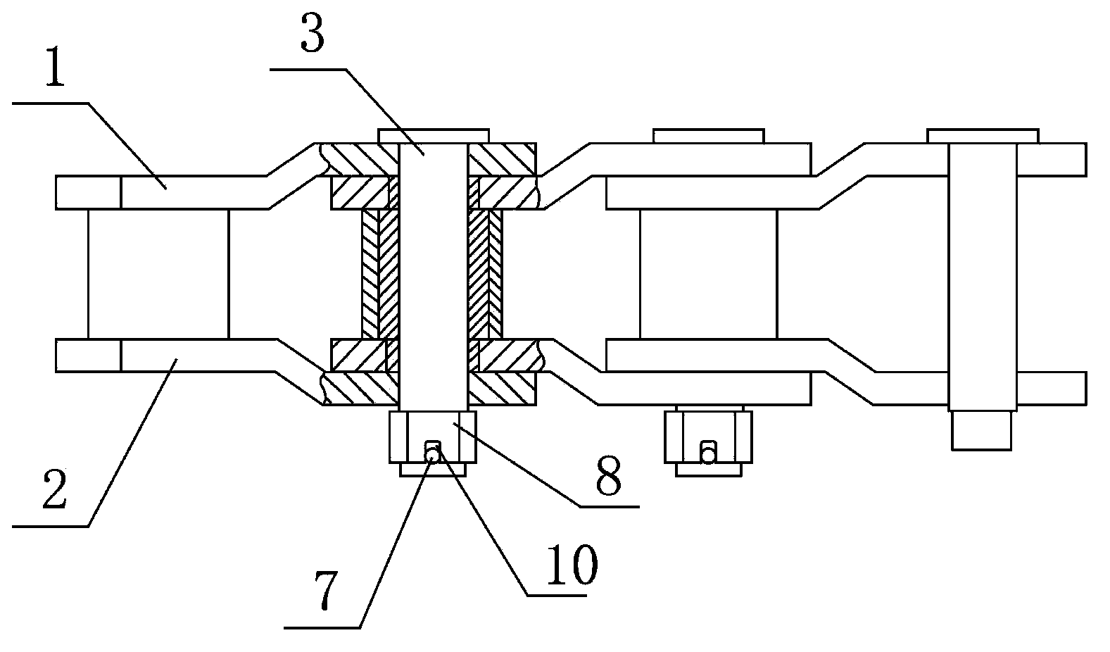
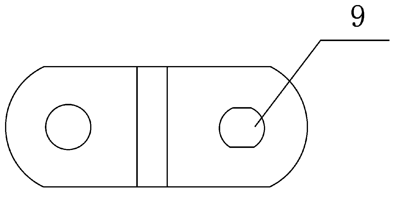
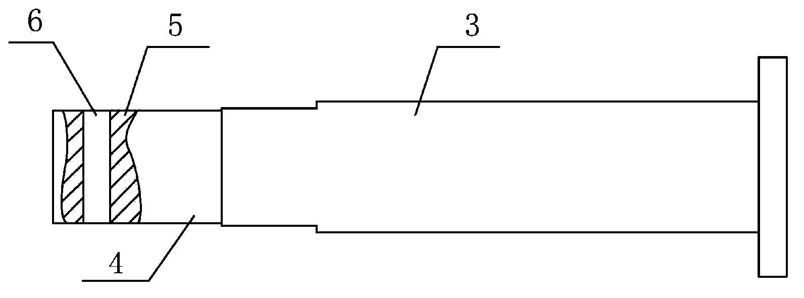
[0010] The present invention will be further explained below in conjunction with accompanying drawing. like figure 1 , figure 2 , image 3 Middle, 1-link A, 2-link B, 3-pin shaft, 4-long flat, 5-thread, 6-cotter pin hole, 7-cotter pin, 8-lock nut, 9-long hole, 10-way slot.

[0011] The chain link A1 and the chain link B2 are connected by the pin shaft 3, the locking end of the pin shaft 3 is provided with a cotter pin hole 6, the locking end of the pin shaft 3 is provided with a long flat 4 and a thread 5, and the long flat 4 runs through the chain link B2 The corresponding elongated hole 9 is provided on the top, and is fixedly connected with the lock nut 8 through the thread 5, and the lock nut 8 is provided with a through groove 10 connected with the cotter pin hole 6, and the cotter pin 7 runs through the through groove 10 And cotter pin hole 6.

[0012] The usage examples of the present invention have been described above in detail, but the content described is only...


PUM


Abstract

The invention provides a cranked link chain which comprises a chain link A, a chain link B, a hinge pin and a split pin. The chain link A is connected with the chain link B through the hinge pin, and a split pin hole is formed in the locking end of the hinge pin. The cranked link chain is characterized in that a long flat piece and a thread, the long flat piece penetrates through a corresponding long hole formed in the chain link B and is fixedly connected with a locknut through the thread, a through groove communicated with the split pin hole is formed in the locknut, and the split pin penetrates through the through groove and the split pin hole. The long flat piece at the locking end of the hinge pin is matched with the long hole in the chain link B, so the hinge pin is prevented from relatively rotating between the chain link A and the chain link B; meanwhile, the hinge pin is connected with the chain link B through the locknut, and then the locknut is locked by the split pin, so the hinge pin can be prevented from moving; in addition, the locknut is resistant to abrasion, and therefore the service life of the cranked link chain is prolonged, and accidents are reduced.

Description

[0001] technical field [0002] The invention belongs to the field of steel strip and steel coil transportation equipment, and in particular relates to a bent plate chain. Background technique [0003] Bending plate chain is a widely used transportation chain, especially in mining machinery, steel rolling machinery and other fields. Especially in the field of steel rolling machinery, the bent plate chain can be used to transport finished strip steel coils. Compared with the use of roller transport, the bent plate chain itself has the characteristics of simple structure, light equipment weight, low maintenance cost, and fewer accident points. [0004] A standard bent plate chain usually uses a pin to connect two chain links, and holes are drilled at the top of the pin to assemble cotter pins to prevent the pin from moving too much and causing the bent plate chain to break. During the use of the bent plate chain, the main reason affecting its life is that when the pin shaft r...

Claims


Application Information

Patent Timeline
Patent Type & Authority Applications(China)
IPC IPC(8): B65G17/38
Inventor 郭换利何宁梁俊杰
Owner TIANJIN TIANZHONG ZHONGZHI TECH ENG CO LTD
Why Eureka
Eureka Blog
Learn More