Linkage type automatic feeding mechanism

A technology of automatic feeding and linkage mechanism, which is applied to conveyors, transportation and packaging, etc., and can solve problems such as high cost, complex structure, and many parts

Inactive Publication Date: 2014-03-26
CHONGQING ZHIRUIDE TECH
View PDF1 Cites 17 Cited by
  • Summary
  • Abstract
  • Description
  • Claims
  • Application Information

AI Technical Summary

Problems solved by technology

[0004] The technical problem solved by the invention is that the existing

Method used


Image

  • Linkage type automatic feeding mechanism

Examples


Embodiment Construction

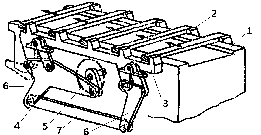
[0011] Such as figure 1 Shown: The automatic feeding mechanism of the connecting rod, including the guide rail 1 that can place the workpiece, the conveying claw 2, the conveying rod 3 and the connecting rod mechanism 4, the conveying rod 3 is set on both sides of the guide rail 1, and the conveying rod 3 is provided with the conveying claw that pushes the workpiece 2. The conveying rod 3 is connected with the link mechanism 4, and the conveying rod 3 moves with the action of the link mechanism 4. The guide rail 1 is a "concave" shape structure. The conveying claw 2 is a wedge-shaped structure, and its conveying claw 2 is plural, and is evenly arranged on the upper end surface of the conveying rod 3 along the conveying direction.

[0012] When working, place the workpiece along the width direction of the guide rail 1, and use the conveying claw 2 on the conveying rod 3 to separate each workpiece. When the connecting rod mechanism drives the conveying rod 3 to move to the proc...


PUM


Abstract

The invention belongs to the field of feeding device, and particularly relates to a linkage type automatic feeding mechanism which comprises a guide rail capable of holding workpieces, conveying pawls, conveying rods and a linkage mechanism. The conveying rods are arranged on two sides of the guide rail, the conveying pawls for pushing workpieces are arranged on the conveying rods which are connected with the linkage mechanism, and the conveying rods move along with action of the linkage mechanism. The workpieces are placed along the width direction of the workpiece, each workpiece is separated from the other by the aid of the conveying pawls on the conveying rods, and when the linkage mechanism drives the conveying rods to move towards a processing station, the conveying pawls drive the workpieces in contact with the same to move. A rack of the linkage mechanism is fixed on a main body seat of the mechanism, two side links are connected with the conveying rods respectively, two ends of a linkage are hinged to the side links respectively, and the conveying rods move along with the side links.

Description

technical field [0001] The invention belongs to the field of feeding devices, in particular to a connecting rod automatic feeding mechanism. Background technique [0002] With the rapid development of the processing industry, enterprises are pursuing efficient, automatic and environmentally friendly production methods. One of the most important means is to use automatic equipment instead of manual operation, which greatly improves production efficiency and reduces labor costs. [0003] In the field of feeding devices, there is an automatic feeding mechanism at this stage. For example, the following technical scheme is disclosed in the public document with the application number ZL200910155572.6. An automatic feeding device for copper rolling teeth, which includes a frame, is characterized in that : the frame is provided with a feeding cylinder mount, a feed cylinder is installed on the feed cylinder mount, a clamping cylinder mount is installed on the feed cylinder, a clamp...

Claims


Application Information

Patent Timeline
IPC IPC(8): B65G25/02
Inventor 严米琪
Owner CHONGQING ZHIRUIDE TECH
Why Eureka
Try Eureka