Pellicle for lithography and a method for making the same

a technology of lithography and pellicle, applied in the field of lithography pellicle and a method for making the same, can solve the problems of deformation of a transferred pattern, rough edges or black stains on the base, damage to dimensions,

Active Publication Date: 2011-06-09
SHIN ETSU CHEM IND CO LTD
View PDF1 Cites 9 Cited by
  • Summary
  • Abstract
  • Description
  • Claims
  • Application Information

AI Technical Summary

Benefits of technology

[0021]Also, a method for manufacturing the pellicle for lithography according to the present invention comprises use of a pellicle frame of which the edges where the upper and lower frame faces respectively join with the inner side faces and the outer side faces of the pellicle frame are chamfered, and in particular the edges where the upper frame face joins with the outer side faces of the pellicle frame have a chamfer of C:0.01 mm-C:0.12 mm, wherein, after attaching a pr

Problems solved by technology

In manufacturing semiconductor devices such as LSI and super-LSI or in manufacturing a liquid crystal display board or the like, a pattern is made by irradiating light to a semiconductor wafer or an exposure original plate (a mask for lithography) for liquid crystal, but if a dust adheres to the exposure original plate, the dust absorbs light or refr

Method used


Image

  • Pellicle for lithography and a method for making the same
  • Pellicle for lithography and a method for making the same
  • Pellicle for lithography and a method for making the same

Examples


example 1

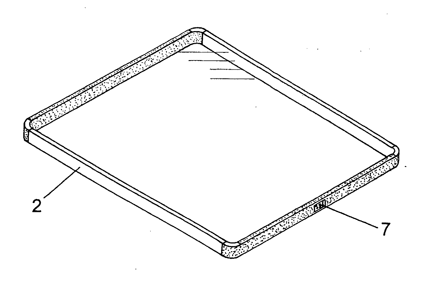
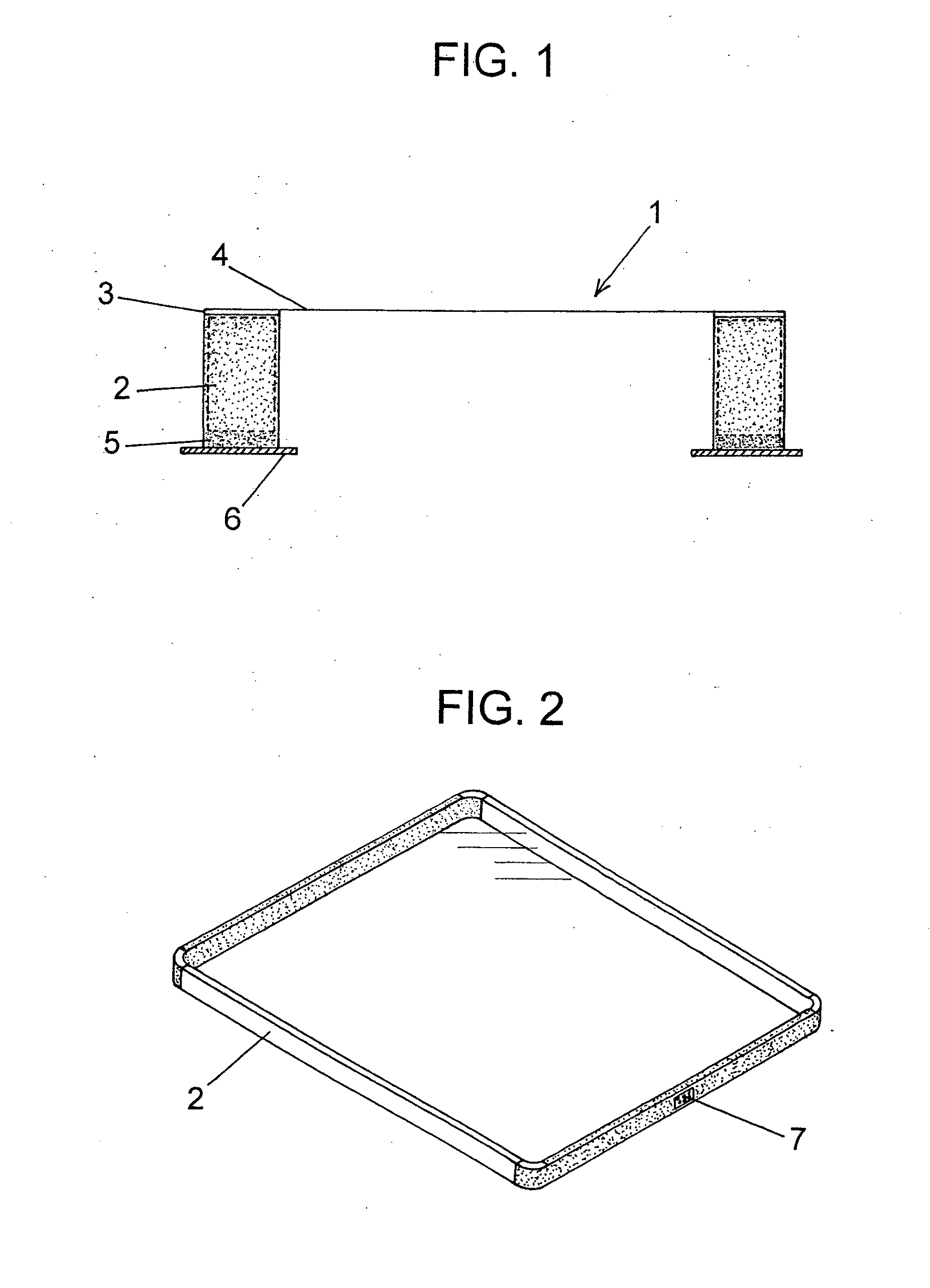
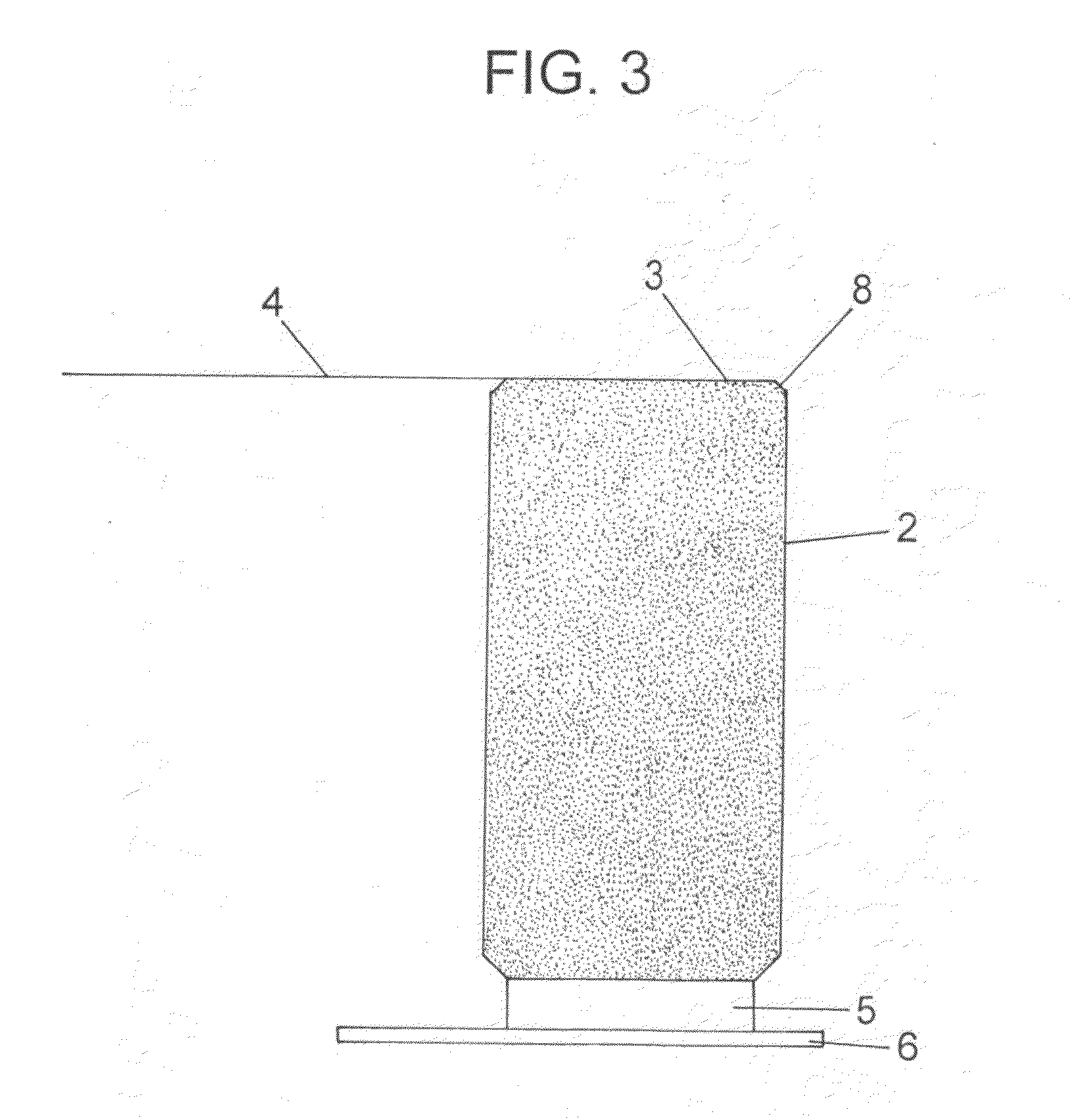
[0052]In the first place, a rectangular frame made of an aluminum alloy A5052 was machined out as the pellicle frame, having the outer peripheral dimension of 474 mm×782 mm, the width of the longer side bar of 7.0 mm, the width of the shorter side bar of 6.0 mm, and the frame thickness, that is the distance between the upper and lower frame faces, of 5.5 mm. The outer edges of the membrane-bonding upper frame face were machined to have chamfer faces of C:0.01 mm, and the other edges of the frame were machined to have chamfer faces of C:0.2 mm. Through the middle portion of one of the bars of the frame were made ten air vent holes each having a diameter of 0.5 mm.

[0053]The surface of this frame was washed, and then roughened in a sand blast machine wherein the frame was subjected to a blasting of glass beads at a blasting pressure of about 147 kPa (1.5 kg / cm2) for a duration of one minute. Thereafter, the frame was dipped in a bath of NaOH aqueous solution for ten seconds for washing...

example 2

[0063]In the first place, a rectangular frame made of an aluminum alloy A7075-T651 was machined out as the pellicle frame, having the outer peripheral dimension of 474 mm×782 mm, the width of the bar of 6.5 mm, and the frame thickness of 7 mm.

[0064]The outer edges of the membrane-bonding upper frame face were machined to have chamfer faces of C:0.1 mm, and the other edges of the frame were machined to have chamfer faces of C:0.2 mm. Through the middle portion of one of the bars of the frame were made ten air vent holes each having a diameter of 0.5 mm.

[0065]The surface of this frame was washed, and then roughened in a sand blast machine wherein the frame was subjected to a blasting of glass beads at a blasting pressure of about 147 kPa (1.5 kg / cm2) for a duration of one minute.

[0066]Thereafter, the frame was dipped in a bath of NaOH aqueous solution for ten seconds for washing, and then the frame was subjected an anodic oxidation in a 14% sulfuric acid aqueous solution at a solution...


PUM

PropertyMeasurementUnit
Lengthaaaaaaaaaa
Diameteraaaaaaaaaa
Diameteraaaaaaaaaa

Abstract

There is provided a pellicle in which the frame is chamfered along all of its horizontal edges (as viewed when the pellicle frame is laid flat), and in particular those edges of the frame where the membrane-bonding frame face meets the external side walls of the frame are chamfered to the extent of C:0.01 mm-C:0.12 mm; in relation to this chamfer, a method is also provided wherein, after attaching a preformed pellicle membrane to the membrane-bonding frame face, the excessive part of the preformed membrane which extends beyond outer edges of the frame face is cut off in a manner wherein a blade of a knife is caused to scour the chamfer over the membrane in a manner such that the knife blade is kept in such an angle that the blade gets in a face-to-face contact with the chamfer face or that the blade touches only that edge of the frame where the chamfer face meets the first frame face while the knife blade is moved along the chamfered edge of the frame.

Description

[0001]The present application claims priority from Japanese Application No. 2009-277340 filed on Dec. 7, 2009, the disclosure of which is hereby incorporated by reference herein in its entirety.FIELD OF THE INVENTION[0002]This invention concerns a pellicle for lithography used as a dust-fender for masks employed in lithographic printing to manufacture semiconductor devices such as LSI and super-LSI, and liquid crystal display board.TECHNICAL BACKGROUND OF THE INVENTION[0003]In manufacturing semiconductor devices such as LSI and super-LSI or in manufacturing a liquid crystal display board or the like, a pattern is made by irradiating light to a semiconductor wafer or an exposure original plate (a mask for lithography) for liquid crystal, but if a dust adheres to the exposure original plate, the dust absorbs light or refracts it, causing deformation of a transferred pattern, roughened edges or black stains on a base, and leads to a problem of damaged dimensions, poor quality, deformed...

Claims


Application Information

Patent Timeline
IPC IPC(8): B05C11/00B26D11/00G03F1/64
CPCG03F1/64Y10T83/0207G03F1/62G03F1/66H01L21/0274H01L21/0337
Inventor NAGATA, YOSHIHIKO
Owner SHIN ETSU CHEM IND CO LTD
Why Eureka
Try Eureka