

Vertical pay-off brake device
A brake device and wire-releasing technology, which is applied in the directions of transportation and packaging, delivery of filamentous materials, thin material processing, etc., can solve problems such as scalding employees, hidden safety hazards, and affecting smooth production
- Summary
- Abstract
- Description
- Claims
- Application Information
AI Technical Summary
Problems solved by technology
Method used
Image

Examples
Embodiment Construction
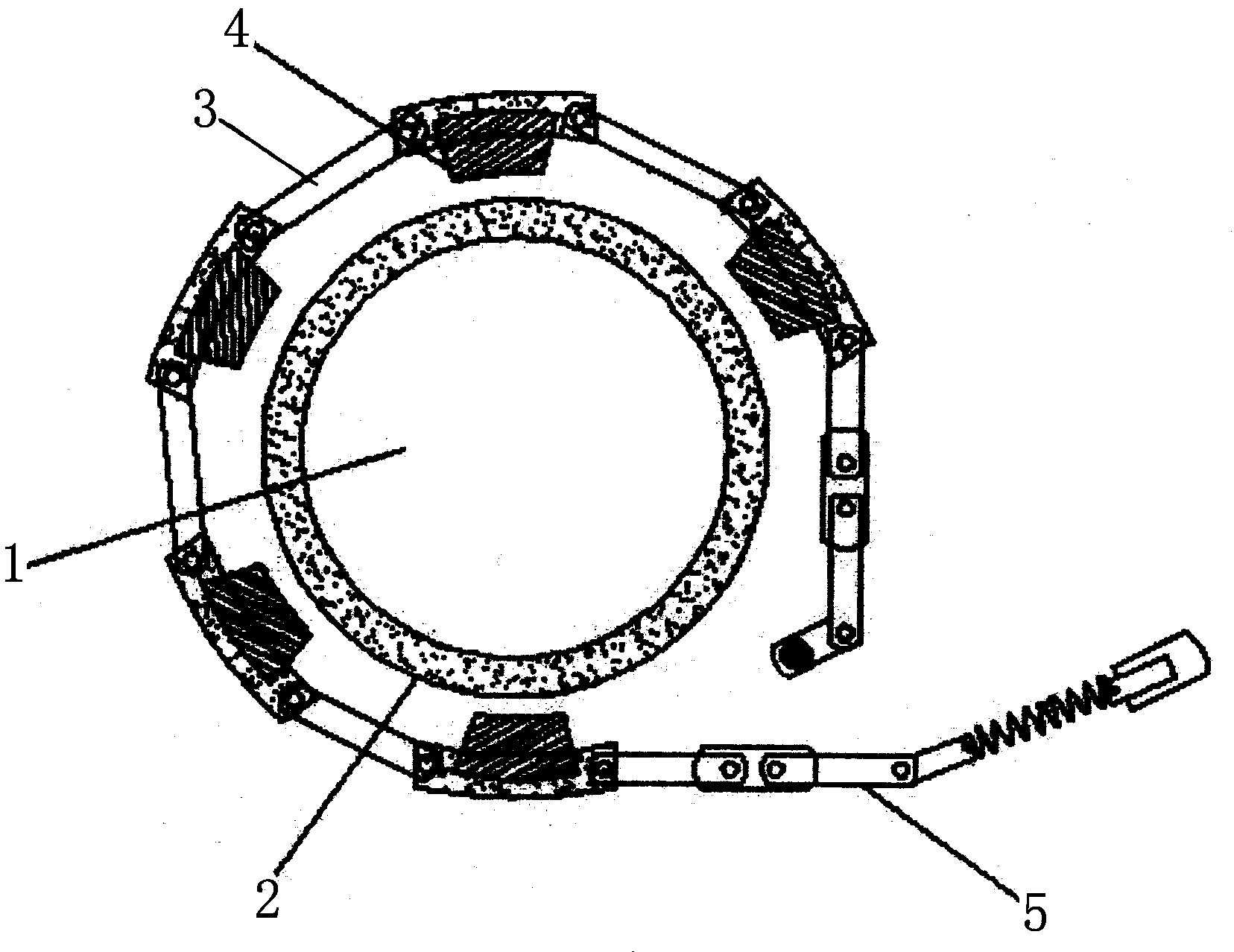
[0009] like figure 1 As shown, the present invention is provided with a brake sleeve 2 on the outer periphery of one end of the pay-off frame 1, a brake belt 3 is arranged on the outer periphery of the brake sleeve 2, and a plurality of brake pads 4 are arranged on the inner edge of the brake belt 3. 4. Corresponding to the brake sleeve 2, one end of the brake band 3 is fixed, and the other end is provided with a lever pressing mechanism 5. Through the above settings, the I-shaped wheel is installed on the rotating shaft of the pay-off frame 1 of the present invention, and the brake pad 4 is pressed against the brake sleeve 2. 4. Loosen the car to set the tension of the pay-off, which avoids the independent rotation of the I-shaped wheel due to inertia, realizes the smooth pay-off, and avoids the drop, disorder and extrusion of the I-shaped wheel pay-off.
PUM
 Abstract
Description
Claims
Application Information