
Buffer device of travelling crab
A cushioning device and crane technology, applied in transportation and packaging, load hanging components, track systems, etc., can solve problems such as inability to change, and achieve the effects of weak cushioning strength, large repulsion force, and high cushioning strength
- Summary
- Abstract
- Description
- Claims
- Application Information
AI Technical Summary
Problems solved by technology
Method used
Image

Examples
Embodiment Construction
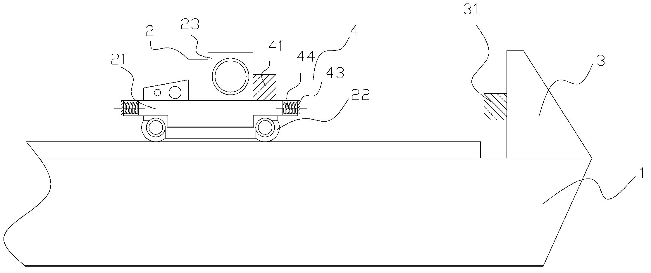
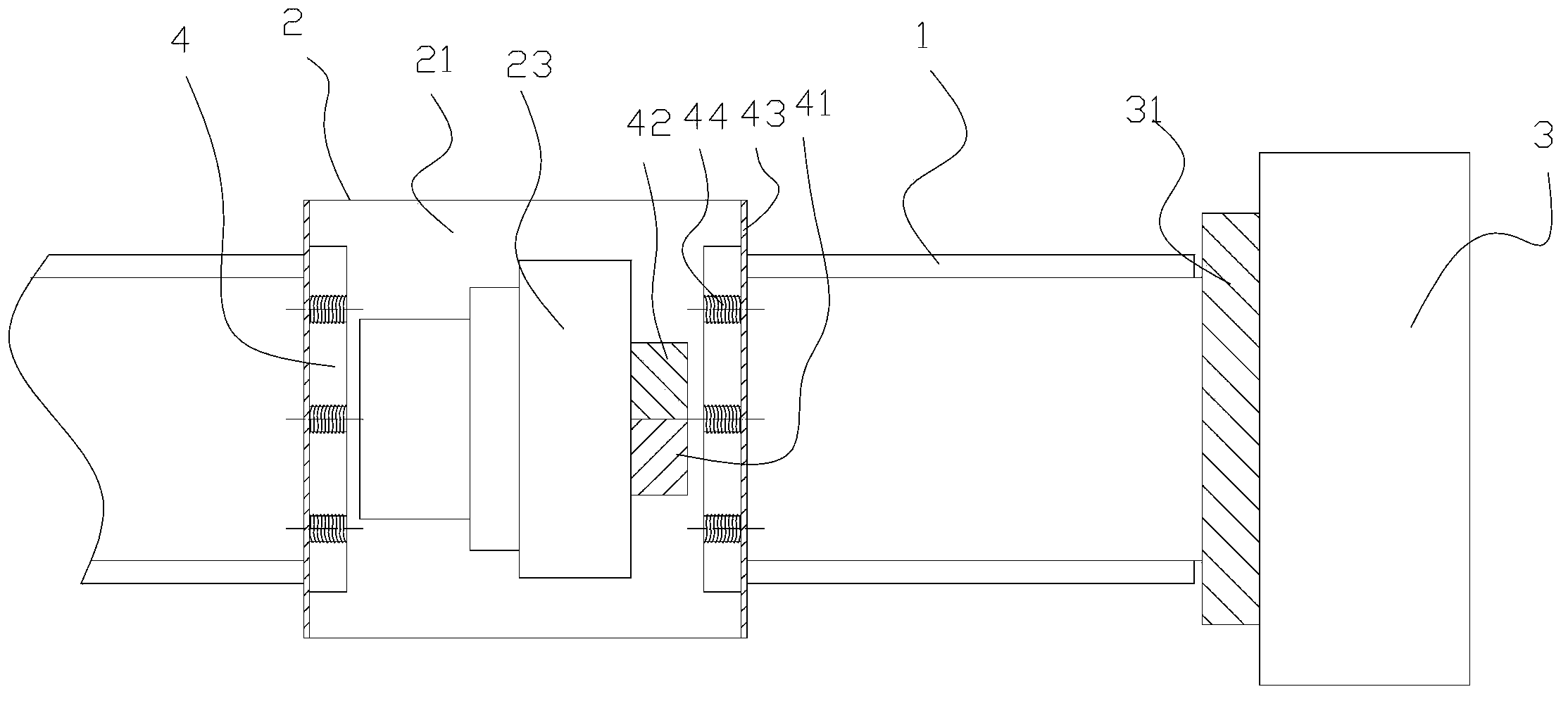
[0019] The present invention as Figure 1-2 As shown, it includes a cart guide rail 1, a crane trolley 2 and two limit baffles 3, the crane trolley 2 is arranged on the cart guide rail 1, and the two limit baffles 3 are respectively arranged on the At the ends of both sides of the cart guide rail 1;
[0020] The crane trolley 2 includes a vehicle frame 21, wheels 22 and several parts 23, the wheels 22 are arranged on the cart guide rail 1 and are movably linked with the vehicle frame 21; several parts 23 are fixedly connected on the frame 21;
[0021] The buffer device 4 is located at the end of the vehicle frame 21 and includes a speed measuring device 41, a current control device 42, two baffle plates 43 and several electromagnets 44;
[0022] The speed measuring device 41 and the current control device 42 are arranged on the vehicle frame 21, the speed measuring device 41 and the current control device 42 are connected, and the speed measuring device 41 can transmit a sig...
PUM
 Abstract
Description
Claims
Application Information