Hydraulic control method and device for top bolt oil cylinder of internal mixer

A control device and mixer technology, which is applied to fluid pressure actuating devices, mechanical equipment, servo motor components, etc., can solve the problems of difficult implementation, complex structure, large volume, etc., and achieve stable control, high control precision, On-site debugging of simple effects

Active Publication Date: 2016-05-25
YIYANG RUBBER PLASTICS MACHINERY GROUP
View PDF7 Cites 1 Cited by
  • Summary
  • Abstract
  • Description
  • Claims
  • Application Information

AI Technical Summary

Problems solved by technology

Since the upper jacking bolt adopts hydraulic control and pneumatic control at the same time, its structure is complicated and the volume is large, so it is difficult to realize in practice

Method used


Image

  • Hydraulic control method and device for top bolt oil cylinder of internal mixer
  • Hydraulic control method and device for top bolt oil cylinder of internal mixer
  • Hydraulic control method and device for top bolt oil cylinder of internal mixer

Examples


Embodiment Construction

[0012] The present invention will be further described below in conjunction with the accompanying drawings and embodiments.

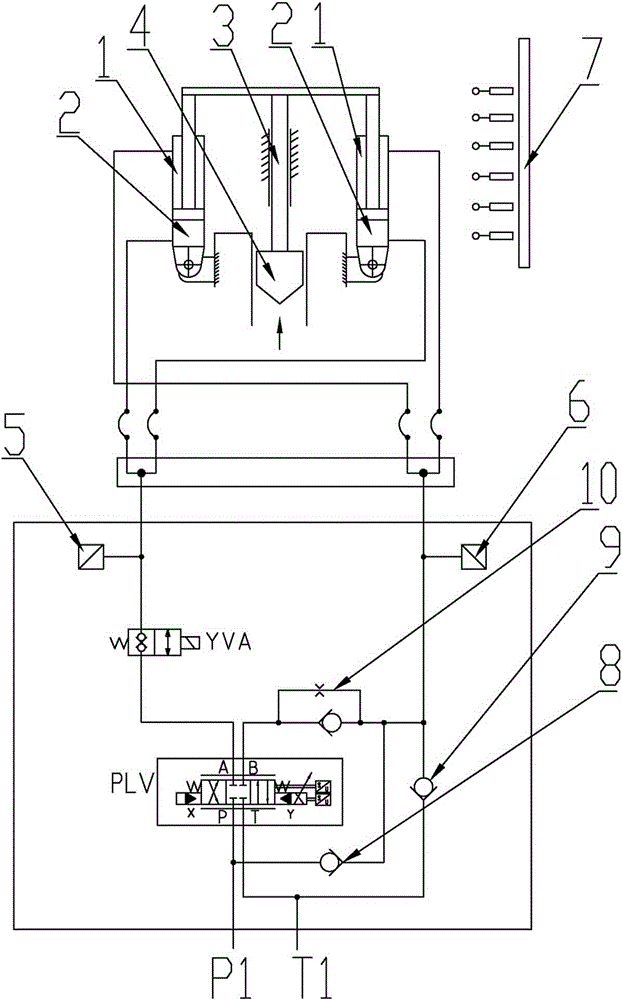
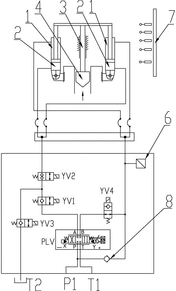
[0013] Depend on figure 1 , figure 2 It can be seen that in the hydraulic control of the top bolt of the existing internal mixer, the working conditions of the lifting weight, weight falling, pressurization, and floating weight all input current signals to the given plate through the upper jacking bolt PLC and switch between open and closed loops. signal to achieve. In the rising and falling control of the weight 4, the open-loop flow control is adopted, that is, the PLC inputs a given signal to the flow given plate, and the hydraulic oil passes through the oil pipe through the oil inlet P1, the proportional servo valve PLV, and the electromagnetic cartridge valve. YVA or proportional servo valve PLV, check valve 10 with damping port feeds oil into rodless chamber 2 or rod chamber 1 of the upward jacking cylinder to realize the rise or fall of upper ...


PUM


Abstract

The invention discloses a hydraulic control method for a ram piston oil cylinder of an internal mixer. According to the method, pressurizing and floating of a pressing lead are achieved, and a control effect of floating of the pressing lead is good. The hydraulic control method is characterized in that the pressure and speed of a ram piston are controlled by a main PLC of the internal mixer, and the pressure control over the ram piston is the pressure control over rod end chambers of the ram piston oil cylinder; a first hydraulic oil path is connected with non-rod end chambers of the ram piston oil cylinder through oil pipes by passing an oil inlet P1, a proportional servo valve PLV, an electromagnetic cartridge valve YV1 and an electromagnetic cartridge valve YV2; the other hydraulic oil path is connected with the rod end chambers of the ram piston oil cylinder through the oil pipes by passing the oil inlet P1, the proportional servo valve PLV and an electromagnetic cartridge valve YV4, and the rod end chambers of the ram piston oil cylinder are connected with the oil inlet P1 through a rising differential one-way valve; an electromagnetic cartridge valve YV3 connected with an oil return opening T2 is further connected between the electromagnetic cartridge valve YV1 and the electromagnetic cartridge valve YV2; an oil inlet P of the proportional servo valve PLV is connected with the oil inlet P1, and an oil return opening T of the proportional servo valve PLV is connected with an oil return opening T1. According to the hydraulic control method, a hydraulic control device for the ram piston oil cylinder is simplified, closed-loop control over the pressure of the ram piston can be truly achieved, and the quality of rubber mixing is improved.

Description

technical field [0001] The invention relates to an internal mixer, in particular to the control of the top bolt of the internal mixer, in particular to a hydraulic control method and device for the top bolt oil cylinder of the internal mixer. Background technique [0002] The internal mixer is the key equipment for processing rubber raw materials into semi-finished rubber in the rubber industry. The top bolt is the core part of the internal mixer. Its main function is to feed the rubber in the mixing chamber through the weight mounted on the top Provide a given pressure, and the pressure weight will produce tracking motion with the volume change of the rubber material, including working conditions such as weight up, weight down, pressurization, and floating weight. At present, there are two types of control for the top bolt on the internal mixer: pneumatic control and hydraulic control. Among them, the hydraulic control method is a control method developed in recent years. ...

Claims


Application Information

Patent Timeline
Patent Type & Authority Patents(China)
IPC IPC(8): F15B1/02F15B13/042B29B7/28
CPCB29B7/183B29B7/246B29B7/283B29B7/7495B29B7/801
Inventor 彭志深林广张燕张宏强杨帆
Owner YIYANG RUBBER PLASTICS MACHINERY GROUP
Why Eureka
Try Eureka