a solenoid valve

A technology of solenoid valve and valve sleeve, applied in the field of solenoid valve, can solve the problems of insufficient electromagnetic force, not very safe, pressure difference, etc.

Inactive Publication Date: 2016-04-20
NINGBO LONGTENG HYDRAULIC COMPONENTS
View PDF7 Cites 0 Cited by
  • Summary
  • Abstract
  • Description
  • Claims
  • Application Information

AI Technical Summary

Problems solved by technology

[0003] Due to the above solenoid valve structure, when the solenoid valve is working, there will be a large pressure difference between the oil inlet 20 and the oil outlet 21. When the solenoid valve is opened, the electromagnetic force of the coil energization is likely to be insufficient to make the moving iron 3 pull the steel ball. The problem of 50 detaching from valve port 51
The method of increasing the pulling force of the moving iron 3 by increasing the electromagnetic force is not very safe

Method used


Image

  • a solenoid valve
  • a solenoid valve
  • a solenoid valve

Examples


Embodiment Construction

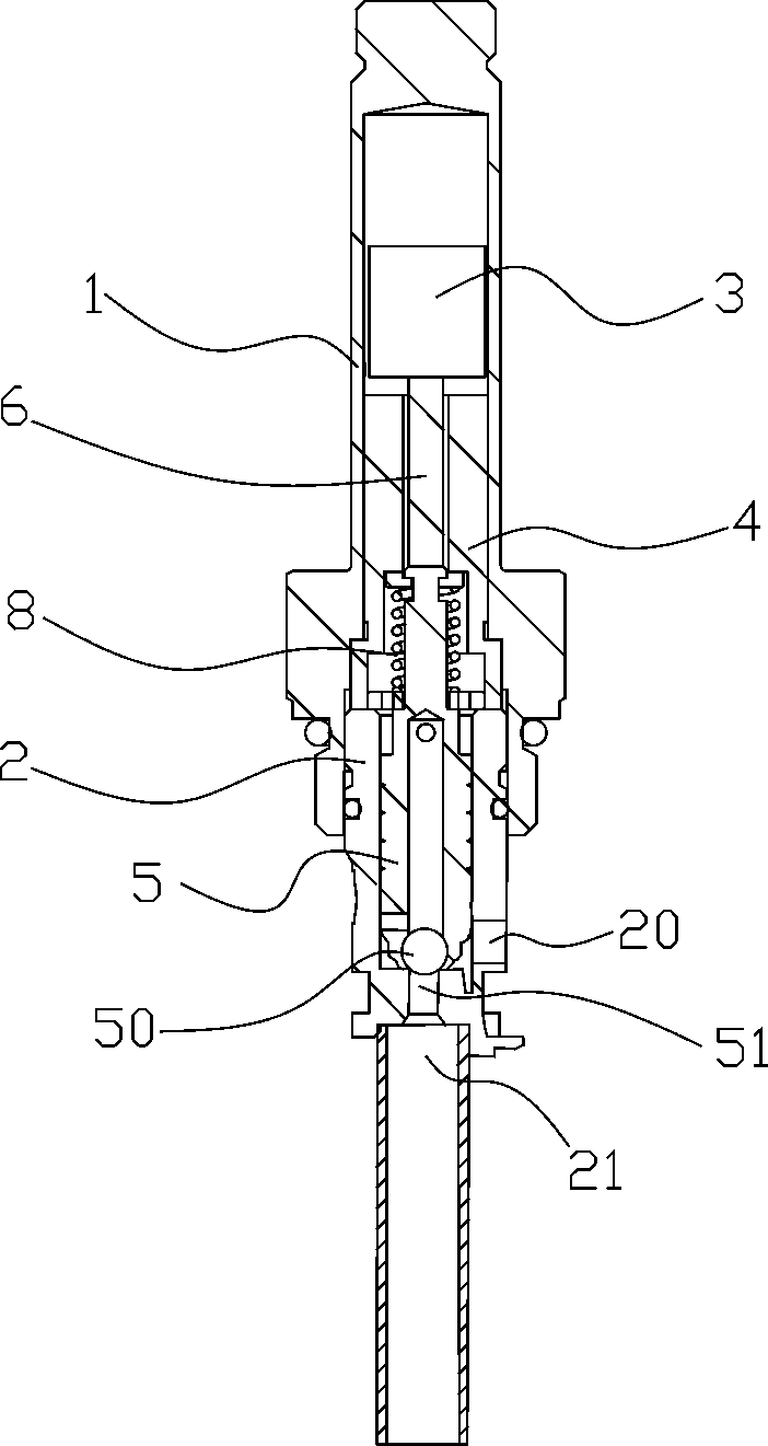
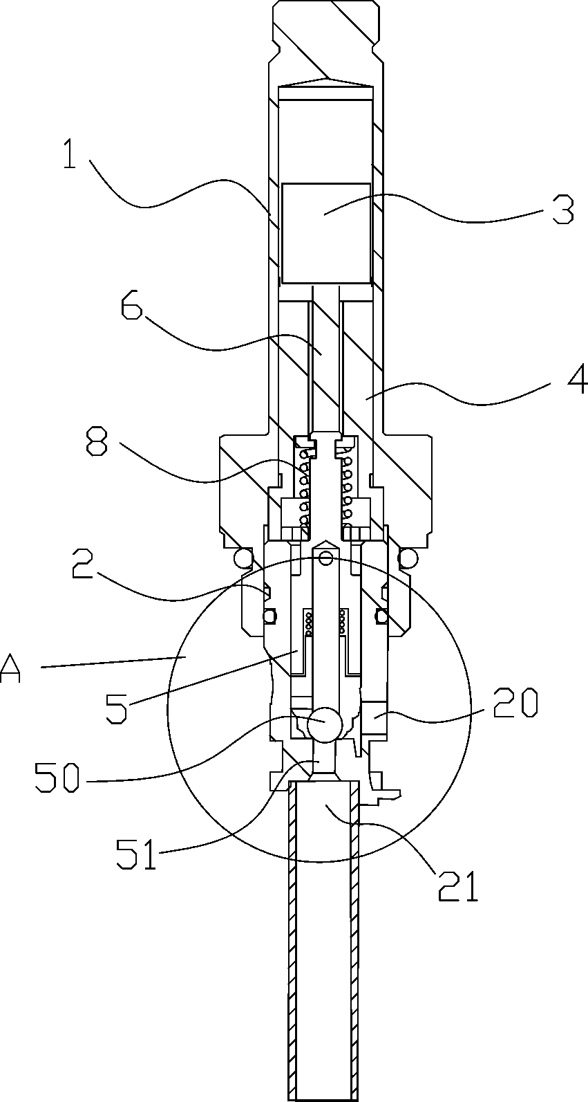
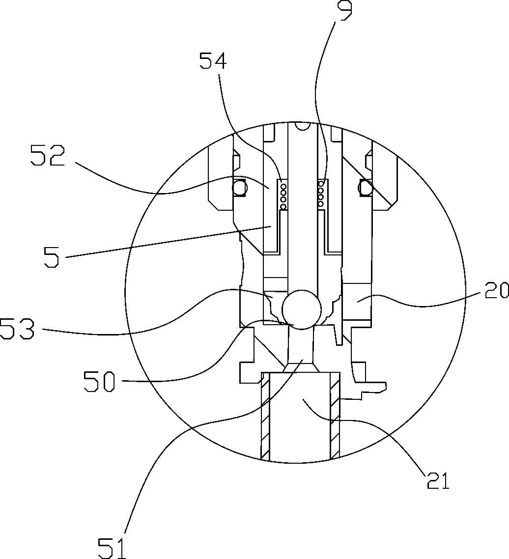
[0011] The present invention will be further described in detail below. In this embodiment, preferably, both the elastic member 9 and the reset member 8 are springs. see Figure 1 to Figure 3 , a solenoid valve, comprising a magnetic sleeve 1, a moving iron 3 is slidably arranged in the hollow cavity of the magnetic sleeve 1, and a fixed iron 4 is slidably arranged in the cavity of the magnetic sleeve 1 at intervals of the moving iron 3; the valve Sleeve 2, the valve sleeve 2 is fixed on the front end of the magnetic sleeve 1, and the end and side wall of the valve sleeve 2 are respectively provided with an oil inlet 20 and an oil outlet connected to the inner cavity of the valve sleeve 21. Coil (not shown in the drawings), the coil is wrapped on the outside of the magnetic sleeve 1, and provides a magnetic field that moves the moving iron 3 to the fixed iron 4 when the coil is energized; the valve core 5 , the spool 5 is slidably arranged in the inner cavity of the valve sle...


PUM


Abstract

The invention discloses an electromagnetic valve, and belongs to the technical field of valves. The electromagnetic valve comprises a valve spool. The valve spool is slidably arranged in an inner cavity of a valve sleeve and is fixedly connected with movable iron by a push rod, an accommodating portion for accommodating a steel ball is arranged at the front end of the valve spool, the steel ball is arranged in the accommodating portion, and a valve port is closed by the steel ball; the valve spool comprises a first portion and a second portion, a slide groove is formed in the second portion, the first portion is slidably arranged in the slide groove, an elastic component is arranged in the slide groove, one end of the elastic component is fixed to the second portion, and the other end of the elastic component is fixed to the first portion. The electromagnetic valve has the advantage that the elastic component is pulled by the first portion of the valve spool, the first portion of the valve spool is provided with certain initial momentum, the second portion of the valve spool is pulled by the elastic component, accordingly, the steel ball in the second portion of the valve spool can be effectively separated from the valve port, and the problem that an existing valve cannot be opened is solved.

Description

technical field [0001] The invention relates to the field of valves, and more specifically, to an electromagnetic valve. Background technique [0002] Traditional solenoid valve structure such as figure 1 , including a magnetic sleeve 1, a moving iron 3 is slidably arranged in the hollow cavity of the magnetic sleeve 1, and a fixed iron 4 is fixedly arranged at a distance from the moving iron 3 in the cavity of the magnetic sleeve 1; the valve sleeve 2, the The valve sleeve 2 is fixed on the front end of the magnetic sleeve 1, and the end and side wall of the valve sleeve 2 are respectively provided with an oil inlet 20 and an oil outlet 21 communicating with the inner cavity of the valve sleeve; the coil (attached Not shown in the figure), the coil is wrapped on the outside of the magnetic sleeve 1, and provides a magnetic field that makes the moving iron 3 move to the fixed iron 4 when the coil is energized; the valve core 5, the valve core 5 slides It is arranged in the...

Claims


Application Information

Patent Timeline
Patent Type & Authority Patents(China)
IPC IPC(8): F16K31/06F16K1/32F16K1/52
CPCF16K1/14F16K1/32F16K31/0665F16K31/0675
Inventor 金红明周衍靖钟艺
Owner NINGBO LONGTENG HYDRAULIC COMPONENTS
Why Eureka
Try Eureka