
Camp stove

A technology of camping stove and outer cylinder, which is applied in the field of camping stoves, can solve the problems of heat loss, burns of users, easy heating of the outer cylinder, etc., and achieve the effect of improving fuel utilization and good heat preservation effect

Inactive Publication Date: 2014-03-26
CHENGDU FLENDA SCI & TECH
View PDF5 Cites 2 Cited by
  • Summary
  • Abstract
  • Description
  • Claims
  • Application Information

AI Technical Summary

Problems solved by technology

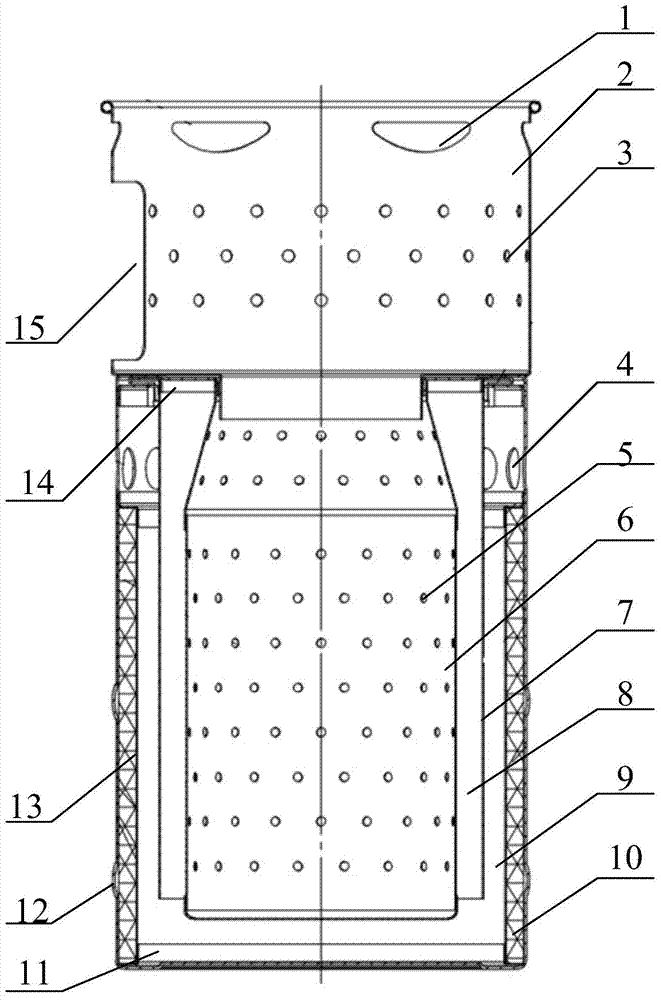
[0003] A camping stove generally includes a camping stove outer cylinder and a combustion cylinder covered inside the camping stove outer cylinder. The combustion cylinder and the camping stove outer cylinder are generally coaxially arranged, and the upper end of the combustion cylinder is fixedly connected to the upper end of the camping stove outer cylinder, and the combustion The bottom of the cylinder is higher than the bottom of the outer cylinder of the camping stove, and the diameter of the combustion cylinder is smaller than that of the outer cylinder of the camping stove, so that a ventilation interlayer is formed between the combustion cylinder and the outer cylinder of the camping stove, and the outer cylinder of the camping stove is provided with a ventilation interlayer The combustion cylinder is provided with a second air inlet communicating with the ventilation interlayer. The combustion cylinder is a place for fuel combustion. Although there is a certain gap between the outer cylinder of the camping stove and the combustion cylinder, the After a period of burning, the outer cylinder of the camping stove is also very easy to get hot, which not only easily causes burns to the user, but also causes a large part of the heat in the combustion cylinder to be lost through the outer cylinder of the camping stove, reducing the temperature of the camping stove. Furnace utilization

Method used


Image

  • Camp stove
  • Camp stove
  • Camp stove

Examples


Embodiment Construction

[0026] The core of the present invention is to provide a camping stove, which can effectively reduce the heat loss of the combustion tube and improve the fire utilization rate of the camping stove while preventing users from being scalded by the outer cylinder of the camping stove.

[0027] In order to enable those skilled in the art to better understand the solution of the present invention, the present invention will be further described in detail below in conjunction with the accompanying drawings and specific embodiments.

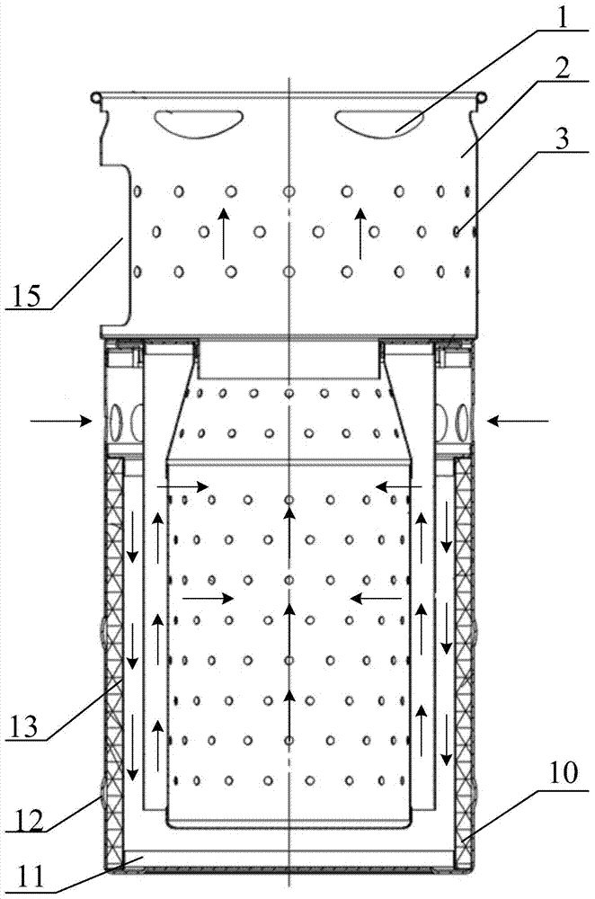
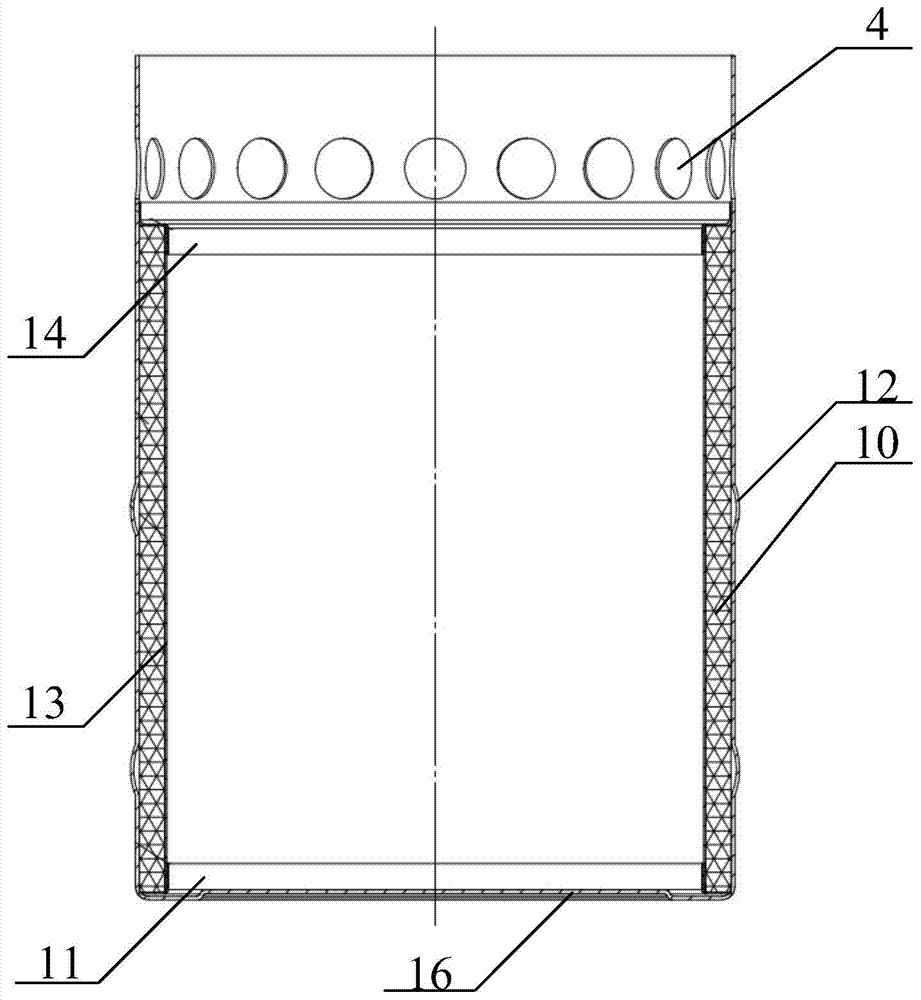
[0028] Please refer to figure 1 and image 3 , figure 1 It is a schematic diagram of the overall structure of the camping stove provided by the embodiment of the present invention, image 3 It is a schematic structural diagram of the outer cylinder of the camping stove provided by the embodiment of the present invention.

[0029] The camping stove provided by the embodiment of the present invention includes a camping stove outer cylinder and a combus...


PUM


Abstract

The invention relates to a camp stove, which comprises a camp stove outer tube and a combustion tube, wherein the combustion tube is arranged inside the camp stove outer tube, in addition, the upper end of the combustion tube is fixedly connected with the upper end of the camp stove outer tube, a ventilation sandwich layer is arranged between the combustion tube and the camp stove outer tube, in addition, a first air inlet and a second air inlet which are communicated with the ventilation sandwich layer are respectively formed in the camp stove outer tube and the combustion tube, and in addition, the camp stove also comprises a heat isolation layer arranged on the inner wall of the camp stove outer tube. The camp stove has the advantages that occurrence of scald injury of users by the camp stove outer tube is avoided, meanwhile, the heat isolation layer can also realize the effect of effectively preventing the heat radiation of the combustion tube to the outside through the camp stove outer tube, and a good heat insulation effect is realized on the combustion tube of the camp stove, so the fuel utilization rate of the camp stove is effectively improved.

Description

technical field [0001] The invention relates to the technical field of outdoor camping tourism equipment production, in particular to a camping stove. Background technique [0002] With the gradual improvement of people's living standards, outdoor camping tourism has become the choice of more and more people. When people spend a long time outdoors, whether it is for picnics or to maintain basic survival needs, it is inevitable. Food is cooked and processed. In response to this demand, camping stoves for cooking and processing food in the wild have appeared on the market. [0003] A camping stove generally includes a camping stove outer cylinder and a combustion cylinder covered inside the camping stove outer cylinder. The combustion cylinder and the camping stove outer cylinder are generally coaxially arranged, and the upper end of the combustion cylinder is fixedly connected to the upper end of the camping stove outer cylinder, and the combustion The bottom of the cylinder...

Claims


Application Information

Patent Timeline
Patent Type & Authority Applications(China)
IPC IPC(8): F24C1/16
Inventor 蒋立维
Owner CHENGDU FLENDA SCI & TECH
Learn More