
A micro-vibration test method for a solar wing drive mechanism

A technology for driving and testing solar wings, which is applied to measuring devices, measuring ultrasonic/sonic/infrasonic waves, instruments, etc., to achieve the effects of improving measurement accuracy, improving adaptability, and ensuring safety

Active Publication Date: 2016-03-16
BEIJING INST OF SPACECRAFT SYST ENG +1
View PDF4 Cites 0 Cited by
  • Summary
  • Abstract
  • Description
  • Claims
  • Application Information

AI Technical Summary

Problems solved by technology

At present, there is no literature report on the micro-vibration test method of this kind of solar wing drive mechanism at home and abroad.

Method used


Image

  • A micro-vibration test method for a solar wing drive mechanism
  • A micro-vibration test method for a solar wing drive mechanism
  • A micro-vibration test method for a solar wing drive mechanism

Examples


Embodiment Construction

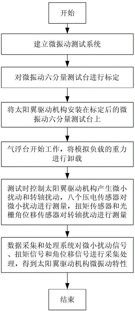
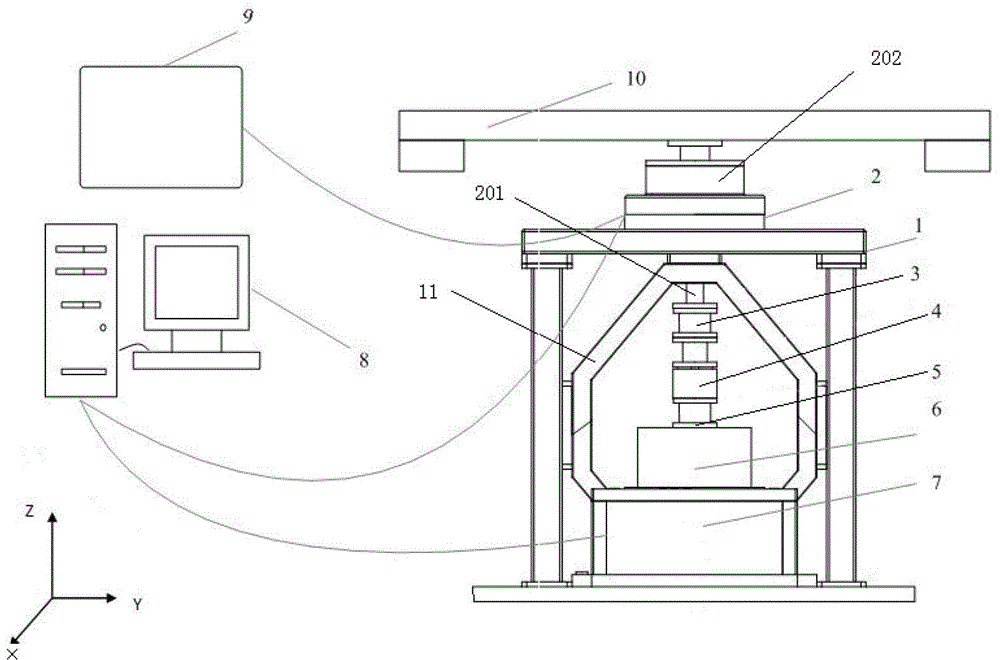
[0018] Such as figure 1 As shown, the present invention first establishes as figure 2 The micro-vibration test system is shown, the test system includes: bracket 1, air bearing table 2, torque sensor 3, linear bearing 4, flange 5, micro-vibration six-component test bench 7, data acquisition and processing system 8, auxiliary system 9 And the simulated load 10, the air bearing table 2 is fixed on the bracket 1 by bolts, the rotating shaft 201 of the air bearing table 2 is fixedly connected with the torque sensor 3, and the torque sensor 3 is fixedly connected with the flange 5 through the linear bearing 4 and makes the axis of the three In a straight line, the linear bearing 4 is used to transmit the torque in the Z direction of the solar wing drive mechanism 6. The micro-vibration six-component test bench 7 is arranged in the support 1 and connected with the support 1 through the frame 11. The micro-vibration six-component test bench 7 will The lower end of the solar wing dr...


PUM


Abstract

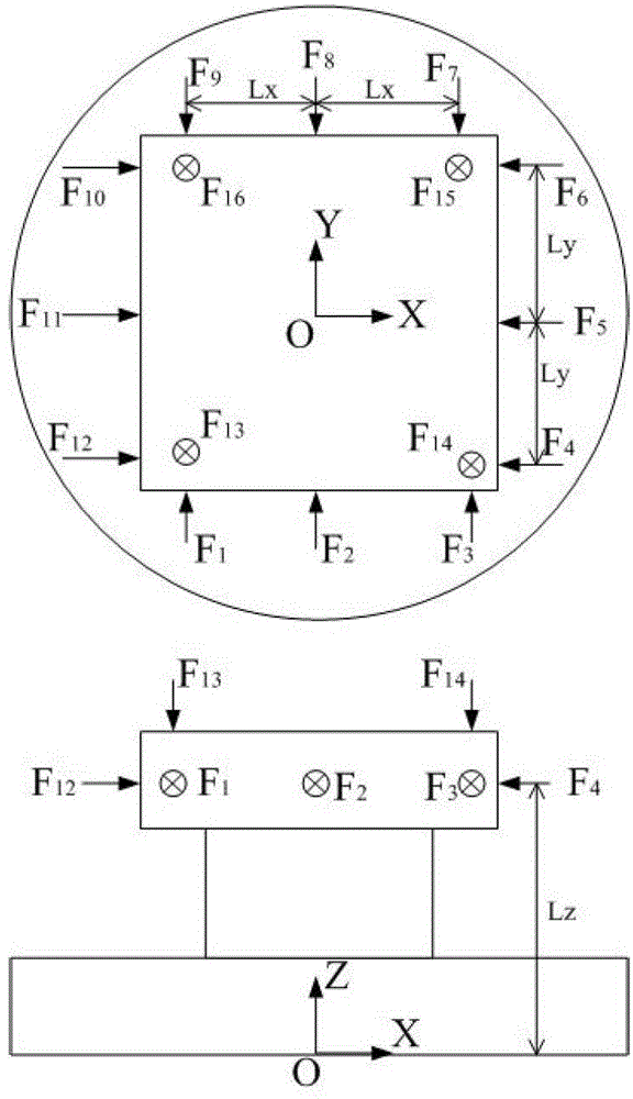
The invention discloses an SADA micro vibration testing method. An air floating table is used for barometric support to overcome the influence of the ground gravity on an SADA, a measuring device is separated from a measured piece during test, and it is not required to mount additional equipment and sensors on the measured piece, thereby not influencing dynamic features of the measured piece, not damaging the structure of the measured piece, and ensuring the safety of the measured piece. Eight common piezoelectric sensors are reasonably arranged, so that micro-disturbance signals in six freedom degrees can be measured by the prior unidirectional piezoelectric sensors, thereby overcoming the problem of lack of high-precision tri-directional sensors, and greatly improving the measurement precision. A disturbance source can be arranged inside or outside a measuring system, so that the adaptability of the measuring system can be improved.

Description

technical field [0001] The invention relates to a micro-vibration testing method, in particular to a micro-vibration testing method of a solar wing driving mechanism in different gravity environments, which belongs to the technical field of vibration testing and can be used for the dynamic measurement of the on-orbit vibration characteristics of the solar wing driving mechanism simulation. Background technique [0002] The main factors affecting satellite jitter and attitude stability include environmental external force interference, attitude maneuvering, and disturbance moments of moving parts on the satellite. The jitter caused by satellite imaging devices and moving parts on the satellite always exists and has a great impact on the imaging quality, so it is necessary to suppress or isolate it by corresponding control means. The active parts on the star mainly refer to the satellite solar wing drive mechanism, such as figure 1 As shown, a rotating shaft is installed at t...

Claims


Application Information

Patent Timeline
Patent Type & Authority Patents(China)
IPC IPC(8): G01H11/08
Inventor 刘凤晶夏明一李果程伟杨文涛陈江攀王成伦赵煜王光远沈中
Owner BEIJING INST OF SPACECRAFT SYST ENG
Learn More