Method for detecting contact pressure between conductive slip ring and conductive brush wire

A contact pressure, conductive slip ring technology, applied in force/torque/work measuring instruments, measuring devices, instruments, etc., can solve the problems of not finding, not collecting data, detecting the contact pressure of conductive slip ring brush wire, etc. Reliable Intuitive Effects

Inactive Publication Date: 2014-03-26
SHANGHAI SPACEFLIGHT INST OF TT&C & TELECOMM
View PDF7 Cites 10 Cited by
  • Summary
  • Abstract
  • Description
  • Claims
  • Application Information

AI Technical Summary

Problems solved by technology

At present, there is no method that can accurately detect the actual contact pressure of conductive slip ring brush wire, and no similar information has been collected at home and abroad.

Method used


Image

  • Method for detecting contact pressure between conductive slip ring and conductive brush wire
  • Method for detecting contact pressure between conductive slip ring and conductive brush wire
  • Method for detecting contact pressure between conductive slip ring and conductive brush wire

Examples


Embodiment Construction

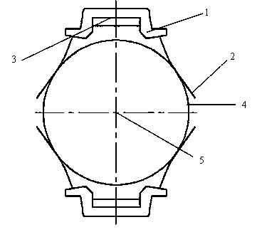
[0018] The working principle of the conductive slip ring-brush combination is shown in figure 1 The brush wire 2 is installed on the brush wire assembly 1, which is fixed on the brush wire assembly installation reference surface 3 of the outer cylinder of the slip ring assembly; the conductive slip ring 4 is installed in the center of the outer cylinder through a bearing, and can rotate around the center of rotation of the slip ring. There is a certain deflection when the brush wire is in contact with the conductive slip ring, so that there is a contact pressure between the brush wire and the conductive slip ring and conducts electricity. The brush wire is connected with the electric circuit of the fixed equipment, and the conductive slip ring is connected with the electric circuit of the rotating equipment, so as to realize the continuous electric transmission from the fixed equipment to the rotating equipment.

[0019] Here, the specific implementation of this patent will be...


PUM


Abstract

The invention provides a method for accurately detecting the contact pressure between a conductive slip ring and a conductive brush wire. The method comprises the following steps: a cross-shaped sliding table is adjusted; a brush wire component to be detected is mounted on a measuring device, and the cross-shaped sliding table is adjusted in the Y direction to enable the brush wire to be detected to be in correct contact with a circular arc of a measuring head according to the working conditions of a product; a connecting rod of the measuring device is slowly swung to enable the brush wire to be in sliding contact with the circular arc of the measuring head, a measuring head system measures and displays the component force, in the force-measuring direction of a sensor, of the contact pressure between the brush wire and the measuring head in real time, the normal direction of a common tangent at the contact point of the brush wire and the circular arc of the measuring head is consistent with the force-measuring direction of the sensor in the swinging measurement process, and the displayed pressure is the contact pressure between the brush wire and the slip ring. The method can accurately detect the practical contact pressure comprehensively formed by factors including the shape error and mounting position error of the brush wire, the elastic coefficient of a brush wire-slip ring contact pair and the like, so that a scientific method is provided for control and adjustment of the contact pressure between the brush wire and the slip ring, the design requirement for reliability of the contact pressure between the slip ring and the brush wire is effectively guranteed.

Description

technical field [0001] The invention relates to a method for detecting the contact pressure of the brush wire of a conductive slip ring, which can accurately simulate the real working state of the brush wire and the slip ring, reproduce the deformation of the brush wire under actual working conditions, and measure the pressure of the brush wire during operation through a measuring device. It provides an effective guarantee for improving the reliability of slip ring brush wire contact compatibility and prolonging the service life of the slip ring brush wire contact compatibility system. It is especially suitable for the control of slip ring-brush wire contact pressure. Where required. Background technique [0002] In some cases where current transmission from fixed equipment to rotating equipment is required, a slip ring assembly is often used to perform electrical transmission in the form of sliding contact between fixed brush wires and rotating slip rings. In order to ensu...

Claims


Application Information

Patent Timeline
Patent Type & Authority Applications(China)
IPC IPC(8): G01L5/00
Inventor 温宇良倪忠标司力琼徐晓东王芳
Owner SHANGHAI SPACEFLIGHT INST OF TT&C & TELECOMM
Why Eureka
Try Eureka