Special optical cable connection device for oil field

A fiber optic cable connection and oil field technology, applied in the coupling of optical waveguide, fiber mechanical structure, etc., can solve the problems of protective layer damage, limited optical cable manufacturing technology level, inner fiber is easily corroded by hydrogen permeation, etc., to ensure continuity, Achieve strong sealing and protection, avoid loss or even breakage

Active Publication Date: 2015-08-26
LASER RES INST OF SHANDONG ACAD OF SCI
View PDF6 Cites 0 Cited by
  • Summary
  • Abstract
  • Description
  • Claims
  • Application Information

AI Technical Summary

Problems solved by technology

On the one hand, the outer protective layer of the optical cable (the outer stainless steel tube, the rubber filling layer and the inner stainless steel tube collectively referred to as the protective layer) will inevitably be damaged during the actual engineering application process. In addition, the corrosive environment of the oil field makes the inner optical fiber easy to be damaged. Hydrogen permeation corrosion, thereby interrupting the communication signal; on the other hand, with the continuous exploitation of oil fields, the depth of oil and gas wells continues to increase, and most of the existing oil wells are several kilometers deep. Thousands of meters, which requires us to connect the optical cable, and special connectors are needed to protect the connection point
The traditional connection device only fixes the outer stainless steel pipe of the optical cable and does not seal the exposed optical fiber well. In the actual application process, after the optical cable is manufactured, for the convenience of transportation and use, the optical cable is usually rolled into a coil, and then rolled into a coil during the downhole process. When the optical cable is straightened, in the process of reeling and straightening, the inner and outer steel pipes will move. In addition, the gravity of the inner stainless steel pipe during the downhole process will also make the inner stainless steel pipe of the optical cable carry the optical fiber relative to the outer stainless steel. If the steel pipe moves, if the movement occurs at the connection of the optical cable, the optical fiber will be broken or have a large bend, resulting in a large loss, and even the optical fiber will be broken due to excessive bending, and the signal transmission will be interrupted.

Method used


Image

  • Special optical cable connection device for oil field
  • Special optical cable connection device for oil field
  • Special optical cable connection device for oil field

Examples


Embodiment Construction

[0016] The technical solution of the present invention will be described in detail below in conjunction with the accompanying drawings and the operation sequence of the connector:

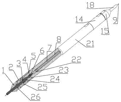
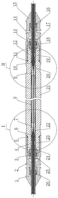
[0017]An oilfield-specific optical cable connection device, the oilfield-specific optical cable connection device consists of a first outer steel pipe fixing and sealing device, a sleeve 21, a second outer steel pipe fixing and sealing device, a first inner steel pipe fixing device, an inner connecting pipe 8 and a second inner Composed of steel pipe fixing devices, the sleeve 21 and the first and second outer steel pipe fixing and sealing devices are sealed through threaded connections and sealing rings; the inner connecting pipe 8 and the first and second inner steel pipe fixing devices are arranged inside the sleeve 21, and the second 1. The fixing device of the second inner steel pipe (4, 12) and the two ends of the inner connecting pipe 8 are respectively connected through the first thread conn...


PUM


Abstract

An optical cable connecting device special for an oil field is composed of a first outer steel tube fixing and sealing device, a sleeve, a second outer steel tube fixing and sealing device, a first inner steel tube fixing device, an inner connecting tube and a second inner steel tube fixing device. Metal deformation of a copper ferrule is used, a front casing tube, a rear casing tube and the inner connecting tube are connected through threads, and the outer diameter of an inner steel tube of an optical cable and the outer diameter of an outer steel tube of the optical cable are different, so that the inner steel tube of the optical cable is fixed. The outer steel tube of the optical cable is doubly fixed and sealed through metal deformation of an inner conic ferrule and an outer conic ferrule. The exposed optical cable is sealed powerfully and thread looseness is prevented through metal deformation of the conic end face at a second end of a reducing connecting tube. According to the optical cable connecting device special for the oil field, the problem that the inner steel tube and the outer steel tube bounce on the connecting portion of the optical cable is well solved and the exposed optical cable and melting points are well sealed and protected.

Description

technical field [0001] The invention relates to a connecting device for connecting two sections of optical cables, and is especially suitable for connecting special optical cables and optical cables in oil fields. Background technique [0002] At present, from the perspective of world energy consumption trends, oil and gas are still the mainstay. The monitoring of parameters such as oil and gas well pressure and temperature is usually realized by electronic products, but the environment of oil and gas wells is extremely complex, mostly high temperature, high pressure and corrosive, making Electronics have extremely limited long-term stability and reliability. Due to the inability to conduct real-time and high-precision monitoring of downhole parameters, well shutdowns caused by failures such as wax plugging, water ingress, and sand outflow occur from time to time. The recovery rate of oil and gas wells is only about 30%, which not only causes waste of resources, but also cos...

Claims


Application Information

Patent Timeline
Patent Type & Authority Patents(China)
IPC IPC(8): G02B6/44G02B6/38
Inventor 赵庆超郭士生王昌刘小会
Owner LASER RES INST OF SHANDONG ACAD OF SCI
Why Eureka
Try Eureka