
Low polarization dependent loss lithium niobate straight-bar waveguide phase modulator and manufacturing method thereof

A phase modulator and related loss technology, which is applied in instruments, nonlinear optics, optics, etc., to achieve the effects of improving electro-optic modulation efficiency and modulation accuracy, easy implementation process, and small polarization-related loss

Active Publication Date: 2014-03-26
BEIJING AEROSPACE TIMES OPTICAL ELECTRONICS TECH
View PDF5 Cites 11 Cited by
  • Summary
  • Abstract
  • Description
  • Claims
  • Application Information

AI Technical Summary

Problems solved by technology

[0006] The purpose of the present invention is to overcome the above-mentioned deficiencies in the prior art, and provide a low polarization-dependent loss lithium niobate straight waveguide phase modulator, which can realize low insertion loss and low polarization-dependent loss of the device at the same time, realizing two The power sharing of the polarization state can effectively eliminate the distortion of the modulation waveform and improve the accuracy of electro-optical modulation

Method used


Image

  • Low polarization dependent loss lithium niobate straight-bar waveguide phase modulator and manufacturing method thereof
  • Low polarization dependent loss lithium niobate straight-bar waveguide phase modulator and manufacturing method thereof
  • Low polarization dependent loss lithium niobate straight-bar waveguide phase modulator and manufacturing method thereof

Examples


Embodiment Construction

[0051] Below in conjunction with accompanying drawing and specific embodiment the present invention is described in further detail:

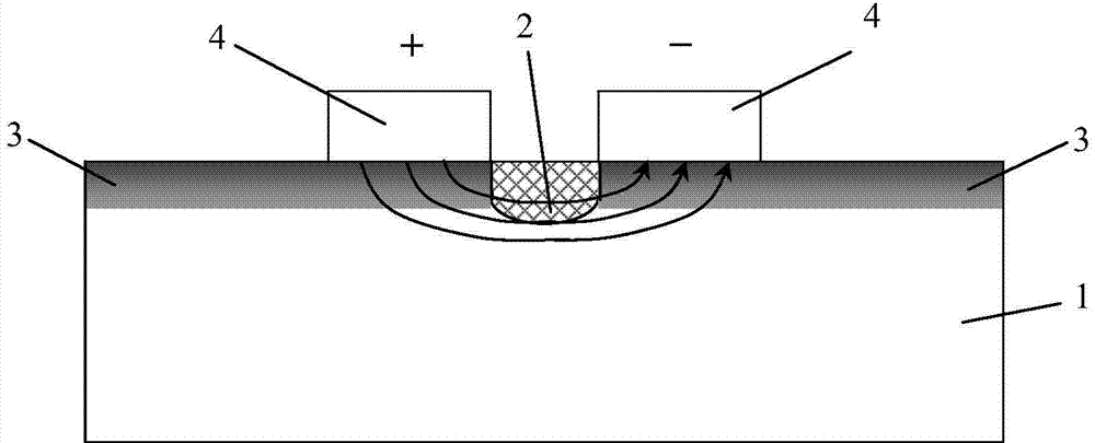
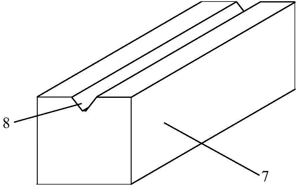
[0052] The low polarization-dependent loss lithium niobate straight strip waveguide phase modulator of the present invention comprises a lithium niobate optical waveguide chip and a first polarization-maintaining pigtail assembly and a second polarization-maintaining pigtail assembly respectively coupled to both ends of the lithium niobate optical waveguide chip, Among them, the first polarization-maintaining pigtail assembly and the second polarization-maintaining pigtail assembly are bonded to one end of the lithium niobate optical waveguide chip, and the first polarization-maintaining pigtail assembly is the input end, and the second polarization-maintaining pigtail assembly is the output end. The lithium niobate optical waveguide chip, the first polarization maintaining pigtail assembly and the second polarization maintaining The second pol...


PUM

PropertyMeasurementUnit
widthaaaaaaaaaa
thicknessaaaaaaaaaa
thicknessaaaaaaaaaa

Abstract

The invention relates to a low polarization dependent loss lithium niobate straight-bar waveguide phase modulator and a manufacturing method of the low polarization dependent loss lithium niobate straight-bar waveguide phase modulator. The low polarization dependent loss lithium niobate straight-bar waveguide phase modulator comprises a lithium niobate optical waveguide chip, a first polarization-maintaining pigtail assembly and a second polarization-maintaining pigtail assembly, wherein the first polarization-maintaining pigtail assembly and the second polarization-maintaining pigtail assembly are bonded to the two ends of the lithium niobate optical waveguide chip in a coupling mode respectively, the lithium niobate optical waveguide chip comprises a lithium niobate substrate, a titanium diffusion waveguide area, annealing external diffusion areas and metal electrodes, an x-cut y-pass chip is adopted for the lithium niobate substrate, the titanium diffusion waveguide area and the annealing external diffusion areas are arranged on the surface layer of the lithium niobate substrate, the annealing external diffusion areas are arranged on the two sides of the titanium diffusion waveguide area respectively, the metal electrodes are arranged on the surfaces of the annealing external diffusion areas, the positive electrode and the negative electrode are symmetrical about the titanium diffusion waveguide area, and the first polarization-maintaining pigtail assembly and the second polarization-maintaining pigtail assembly respectively comprise a first polarization-maintaining optical fiber and a first optical fiber fixing block. The low polarization dependent loss lithium niobate straight-bar waveguide phase modulator achieves low insertion loss and low polarization dependent loss of a device at the same time, and achieves power even distribution of two polarization states, the situation of modulation waveform distortion is effectively eliminated, and accuracy of electro-optical modulation is improved.

Description

technical field [0001] The invention relates to a preparation method of a lithium niobate-based integrated optical device, in particular to a low polarization-dependent loss lithium niobate straight waveguide phase modulator and a preparation method thereof. Background technique [0002] The low polarization-dependent loss lithium niobate straight waveguide phase modulator can simultaneously transmit TE and TM modes, and can simultaneously modulate the phases of these two modes. This feature makes it suitable for optical fiber sensing, especially for optical fiber current sensors. Very popular in development. Using this device, a simple collinear optical fiber current sensor optical path can be formed. Compared with other square optical path schemes such as Sagnac optical path scheme, the optical path of this scheme has smaller temperature error and linear vibration error, no angular vibration error, and the best time reciprocity. Therefore, the modulator with low polariza...

Claims


Application Information

Patent Timeline
Patent Type & Authority Applications(China)
IPC IPC(8): G02F1/035
Inventor 郑国康夏君磊刘福民黄韬汪飞琴关涛
Owner BEIJING AEROSPACE TIMES OPTICAL ELECTRONICS TECH
Learn More