Full optical fiber integrated optical power monitor and manufacturing method thereof

A production method and optical power technology, applied in the coupling of optical waveguides, electromagnetic wave transmission systems, electrical components, etc., can solve the problems of large mutual interference, difficult production methods, large volume, etc., and achieve the effect of reducing costs and low processing costs

Inactive Publication Date: 2011-11-23
JINAN UNIVERSITY
View PDF5 Cites 1 Cited by
  • Summary
  • Abstract
  • Description
  • Claims
  • Application Information

AI Technical Summary

Problems solved by technology

However, the disadvantages of discrete components are that the insertion optical loss is large, the power consumption is large, and the mechanical structure leads to a large volume when forming a multiplexing system, etc.
This technical solution has the advantages of high integration and small size, but because the variable optical attenuator and the optical power monitor are made on the same polishing area, the mutual interference is large, and the optical power monitor will be affected by the variable optical attenuator. great interference; in addition, it is extremely difficult and expensive to manufacture by evaporating flat plate electrodes on optical fibers

Method used


Image

  • Full optical fiber integrated optical power monitor and manufacturing method thereof
  • Full optical fiber integrated optical power monitor and manufacturing method thereof
  • Full optical fiber integrated optical power monitor and manufacturing method thereof

Examples


Embodiment 1

[0054] In this embodiment, a single-mode 9 / 125um optical fiber is used.

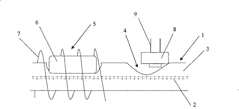
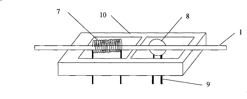
[0055] Such as figure 1 As shown, an all-fiber integrated optical power monitor of the present invention has a variable optical attenuator and an optical power monitor on the optical fiber 1 . The variable optical attenuator polishing area 5 covered with thermophotopolymer 6 is placed in a U-shaped groove (not shown in the figure), and the variable optical attenuator polishing area 5 is polished into a D-shaped fiber segment, which The polishing area is covered with a polymer 6 with a negative thermo-optic coefficient, and a heating resistance wire (also called an electrode) 7 is spirally wound around the periphery to form a variable optical attenuator. The polishing area 4 of the optical power monitor is polished into a V shape, and a photodetector 8 is arranged on the outside.

[0056] A method for manufacturing an all-fiber integrated optical power monitor includes the following steps:

[0057] (1)...


PUM


Abstract

The invention discloses a full optical fiber integrated optical power monitor and a manufacture method thereof. The full optical fiber integrated optical power monitor comprises an optical power monitor and a variable optical attenuator; a cladding of a section of optical fiber is provided with a first light splitting notch and a second light splitting notch between which the distance is 5-25mm; the first light splitting notch is a leakage light path of the variable optical attenuator; and the second light splitting notch is a leakage light path of the optical power monitor. The full optical fiber integrated optical power monitor is manufactured by a side polishing method, the processing cost is low, and the full optical fiber integrated optical power monitor is taken as an integrated substrate, so that the cost of an integrated device is greatly reduced. The full optical fiber integrated optical power monitor has the advantage of capability of being controlled electrically, saves an optical fiber core cutting and mechanical driving mechanism of a mechanical optical power monitor, has low inserting loss and small back reflection electrode, improves reliability of the device and reduces the packaging volume of the device.

Description

technical field [0001] The invention relates to an optical fiber optical power monitor, in particular to an integrated optical power monitor of an optical fiber that integrates a variable optical attenuator and an all-fiber optical power monitor on one optical fiber, and simultaneously has the functions of monitoring and controlling optical power. Monitor and manufacturing method thereof. The invention belongs to the technical field of optical fiber communication, optical fiber sensing and optical fiber device. Background technique [0002] The optical power monitor is one of the key components required by the DWDM (dense wavelength division multiplexing) of the optical network and the all-optical network. In optical network applications, the management of each optical path, especially the optical power in the optical fiber, is an important technical content. For example, in an optical fiber amplifier, in order to ensure good detection characteristics of the system, it is ...

Claims


Application Information

Patent Timeline
Patent Type & Authority Patents(China)
IPC IPC(8): G02B6/42H04B10/08H04B10/071H04B10/079
Inventor 陈哲潘昊张凌童肖雅婷覃家荣
Owner JINAN UNIVERSITY
Why Eureka
Try Eureka