A split-type manufacturing method of a micro-imprinting mold

A manufacturing method and micro-embossing technology, which is applied to the photoplate-making process, instruments, optics, etc. of the pattern surface, and can solve the problems of destroying the mold pattern, difficulty in demoulding, poor repeatability, etc.

Inactive Publication Date: 2016-09-21
NANJING UNIV OF SCI & TECH
View PDF7 Cites 0 Cited by
  • Summary
  • Abstract
  • Description
  • Claims
  • Application Information

AI Technical Summary

Problems solved by technology

The SU8 negative photoresist used in UV-LIGA technology is very sensitive to photolithography process parameters and has poor repeatability, especially the cross-linked polymer formed by SU photoresist after exposure and electroforming process, which is difficult to remove , which limits the application
However, it is more difficult to perform micro-electroforming directly from silicon in the silicon deep etching process.
[0004] In addition, integral micro-precision machining, LIGA technology, and quasi-LIGA technology cannot process the side walls of the pattern to improve the smoothness due to the small distance between the concave and convex patterns of the processed mold.
Unsmooth side walls can easily cause difficulty in demoulding after imprinting, and even damage the mold or the pattern after embossing during the demoulding process

Method used


Image

  • A split-type manufacturing method of a micro-imprinting mold
  • A split-type manufacturing method of a micro-imprinting mold
  • A split-type manufacturing method of a micro-imprinting mold

Examples


Embodiment 1

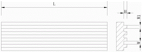
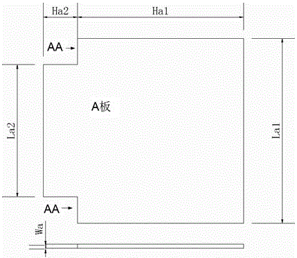
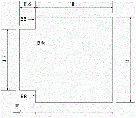
[0063] (1) According to figure 1 In the imprinted micro-groove pattern shown, the groove width W is 0.01 mm, the height H is 0.5 mm, the length L is 190 mm, and the interval W1 is 0.01 mm. Design the processing modules required to manufacture molds. The processing module consists of a board (eg figure 2 shown) Board B (as image 3 As shown), the number of A boards is 250, and the number of B boards is 250. Among them, A board and B board are composed of upper and lower parts respectively. The cuboid structure in the lower part of plate A and B has the same length, width and height, and the cuboid structure in the upper part has the same length and width; the lower part of A plate Ha1, La1 and Wa are 290mm, 200mm and 0.01mm respectively, and the lower part of B plate is Hb1 , Lb1 and Wb are 290mm, 200mm and 0.01mm respectively; part Ha2 on board A is 10mm, La2 is 190mm, Wa is 0.01mm, part Hb2 on board B is 9.5mm, Lb2 is 190mm, and Wb is 0.01mm.

[0064] (2) Machining the m...

Embodiment 2

[0067] A split-type manufacturing method of a micro-imprinting mold, the method comprising the following steps:

[0068] (1) According to Figure 5 The imprinted micro-groove pattern shown has a groove width of 0.3 mm, a depth of 0.5 mm, and a spacing of 0.3 mm. The length of the groove is 100mm, and the processing module of the required manufacturing mold is designed. The processing module consists of a board (eg Image 6 shown) Board B (as Figure 7 As shown), the number of A boards is 6, and the number of B boards is 7. The A board and B board are composed of upper, middle and lower parts respectively. The upper and lower parts are cuboid structures with equal width and different length and height, and the middle part is trapezoidal The upper bottom of the trapezoid is equal in length to the part of the cuboid structure on the board, the length of the lower bottom is equal to the part of the cuboid structure under the board, and the upper, middle and lower parts are inte...

Embodiment 3

[0072] A split-type manufacturing method of a micro-imprinting mold, the method comprising the following steps:

[0073] (1) According to Figure 9 For the embossed micro-rectangular pattern shown, the rectangle protrudes 0.3 mm high and 0.5 mm wide and long. The interval between the rectangles is 0.5mm, and the processing module of the required manufacturing mold is designed. The processing module consists of a rod (eg Figure 10 shown) B stick (as Figure 11 shown) C stick (as Figure 12 As shown), wherein rod A and rod B are cuboid structures with a square base, rod C is a cuboid structure, and the sides of the cuboid structure of rod A, rod B and rod C are equal in length but unequal in height; the cuboid structure of rod A is The length, width and height are 0.5mm, 0.5mm and 10.3mm respectively, the length, width and height of the B-bar cuboid structure are 0.5mm, 0.5mm and 10mm respectively, and the length, width and height of the C-bar cuboid structure are 0.5mm , ...


PUM

PropertyMeasurementUnit
radiusaaaaaaaaaa
heightaaaaaaaaaa
lengthaaaaaaaaaa

Abstract

The invention discloses a split type manufacturing method of a micro-imprinting mould. The method comprises the following steps: designing required processing modules according to target patterns of an imprinting mould, wherein the distance between the single patterns of the target patterns of the imprinting mould is less than 1 mm, at least one dimension of the sizes of the single patterns is less than 1 mm, the modules comprise modules A and B, and the number of the modules is not less than 1; mechanically processing the modules A and B and module frames corresponding to the modules; finally combining and fixing the modules A and B with the corresponding module frames to form the micro-imprinting mould, wherein the modules A and B are arranged in a staggered manner, no gap is formed between the modules A and B, and the modules A and B are different in height.

Description

technical field [0001] The invention relates to a manufacturing method of a micro-imprinting mold, in particular to a split-type manufacturing method of the micro-imprinting mold. Background technique [0002] Microimprinting technology is one of the commonly used techniques in microreplication. Micro-imprinting technology only needs to prepare a template (mold), and many replicas can be processed quickly, cheaply and conveniently. It also has the advantages of processing three-dimensional structural patterns and processing different materials. [0003] The replication of information in micro-imprinting is a difficult point, and the manufacture of molds is the way to replicate information. At present, the methods commonly used in micro-imprinting molds include: integral micro-precision machining, LIGA technology, and quasi-LIGA technology. Micro-precision machining technology requires expensive precision machining equipment, while LIGA technology requires expensive synchro...

Claims


Application Information

Patent Timeline
Patent Type & Authority Patents(China)
IPC IPC(8): G03F7/00
Inventor 张新平陈珊陈扶桑博荣于望
Owner NANJING UNIV OF SCI & TECH
Why Eureka
Try Eureka