
A three-core separately excited three-phase magnetron reactor

A magnetron reactor and iron core column technology, which is applied in the field of three-iron core column separately excited three-phase magnetron reactor, can solve the problems of limiting the promotion and application of the magnetron reactor, high harmonic content of working current, and low material utilization. , to achieve the effect of material saving, low magnetic field harmonic content and low cost

Inactive Publication Date: 2016-08-17
SHANDONG UNIV
View PDF4 Cites 0 Cited by
  • Summary
  • Abstract
  • Description
  • Claims
  • Application Information

AI Technical Summary

Problems solved by technology

However, at present, all three-phase magnetron reactors have a three-phase six-column structure, which has complex structure, large volume, low material utilization, and high harmonic content in the working current, which limits the promotion and application of magnetron reactors.

Method used


Image

  • A three-core separately excited three-phase magnetron reactor
  • A three-core separately excited three-phase magnetron reactor
  • A three-core separately excited three-phase magnetron reactor

Examples


Embodiment Construction

[0023] The present invention is described in detail below in conjunction with accompanying drawing:

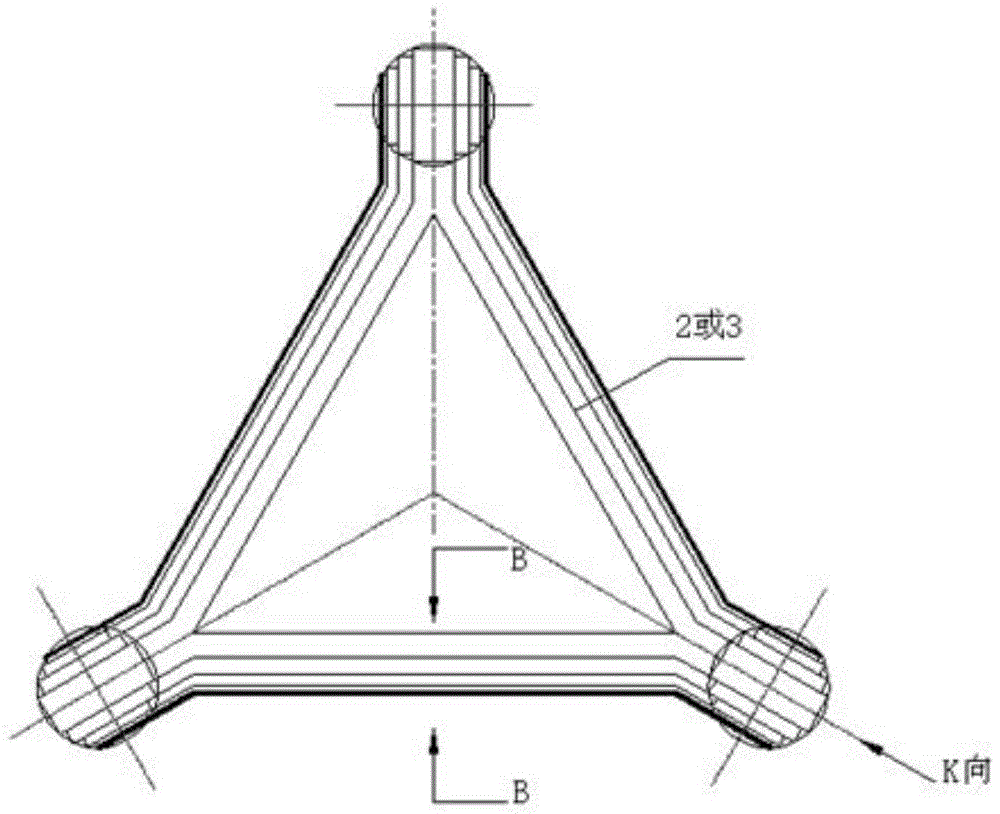
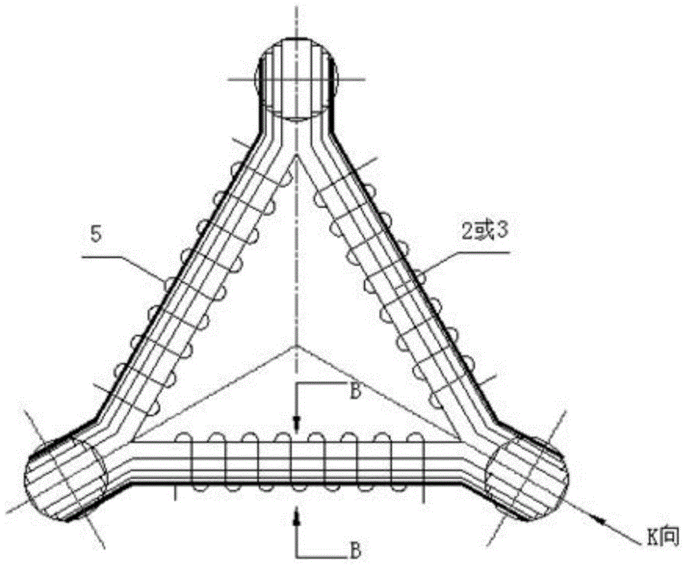
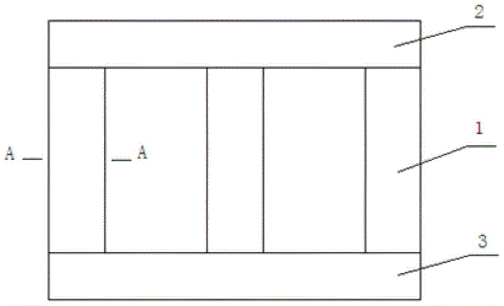
[0024] Such as Figure 1-5 As shown, a three-core separately excited three-phase magnetron reactor includes three main core columns 1, an upper yoke 2, a lower yoke 3, three working windings 4, an upper yoke control winding 5 and a lower yoke control winding 5 , the three main core columns 1 are provided with three working windings 4, the upper yoke 2 and the lower yoke 3 are respectively provided with an upper yoke control winding 5 and a lower yoke control winding 5, and the upper yoke 2 and the lower yoke 3 are plugged in respectively On the two ends of the three main core columns 1, the two ends of the core pieces of the upper yoke 2 and the lower yoke 3 are folded into obtuse angles to form a structure with a straight line at the end and a triangle in the middle. By controlling the upper and lower yokes, the winding 5 The DC current can change the saturation degree of th...


PUM


Abstract

The invention discloses a three-core-limb separate-excitation three-phase magnetically-controlled reactor. The three-core-limb separate-excitation three-phase magnetically-controlled reactor comprises three main core limbs, an upper yoke, a lower yoke, three working windings, an upper yoke control winding, a lower yoke control winding and the like. The main core limbs are formed by stacking silicon steel sheets, and the cross sections of the main core limbs are round inscribed multistage rectangular sections. The two ends of an upper yoke iron core sheet and the two ends of a lower yoke iron core sheet are folded into obtuse angles and connected to the three main core limbs in an inserted mode, and thus a structure with the ends being linear and the middle being triangular is formed. The three main iron limbs are sleeved with the working windings, and the upper yoke and the lower yoke are sleeved with the control windings respectively. According to the magnetically-controlled reactor, the saturation degree of the iron yokes are changed by controlling the direct current of the upper yoke control winding and the lower yoke control winding, the reactance value can be adjusted continuously, and thus the working current of the three-phase magnetically-controlled reactor can be adjusted in a stepless mode. The reactor is simple in structure and good in manufacturability, material is saved, cost is reduced, and meanwhile the harmonic content in the working current is substantially reduced.

Description

technical field [0001] The invention relates to a separately excited three-phase magnetron reactor with three core columns. Background technique [0002] Reactor is a reactive power adjustment equipment widely used in power system. Most of the early reactors were fixed-value reactors, and their reactance value was fixed or adjustable in steps. With the advancement of technology and the actual needs of power systems, countries around the world have successively developed various controllable reactors, of which the magnetic control controllable reactor is one of them, including AC control reactors, DC control reactors, magnetic valve reactor, etc. However, at present, the three-phase magnetron reactor is a three-phase six-column structure, which has complex structure, large volume, low material utilization, and high harmonic content in the working current, which limits the promotion and application of magnetron reactors. . Contents of the invention [0003] In order to so...

Claims


Application Information

Patent Timeline
Patent Type & Authority Patents(China)
IPC IPC(8): H01F27/24H01F27/30
Inventor 李光友赵耀
Owner SHANDONG UNIV
Learn More