Airborne remote antenna mounting device

A technology of mounting device and antenna fixing device, applied in the direction of antenna support/mounting device, etc., can solve problems such as poor portability, and achieve the effects of improving shielding performance, reducing space requirements, and convenient disassembly and assembly

Active Publication Date: 2014-03-26
NANJING UNIV OF AERONAUTICS & ASTRONAUTICS
View PDF9 Cites 5 Cited by
  • Summary
  • Abstract
  • Description
  • Claims
  • Application Information

AI Technical Summary

Problems solved by technology

However, the scope of this patent is limited to the test circuit, and the portability is poor

Method used


Image

  • Airborne remote antenna mounting device
  • Airborne remote antenna mounting device
  • Airborne remote antenna mounting device

Examples


Embodiment Construction

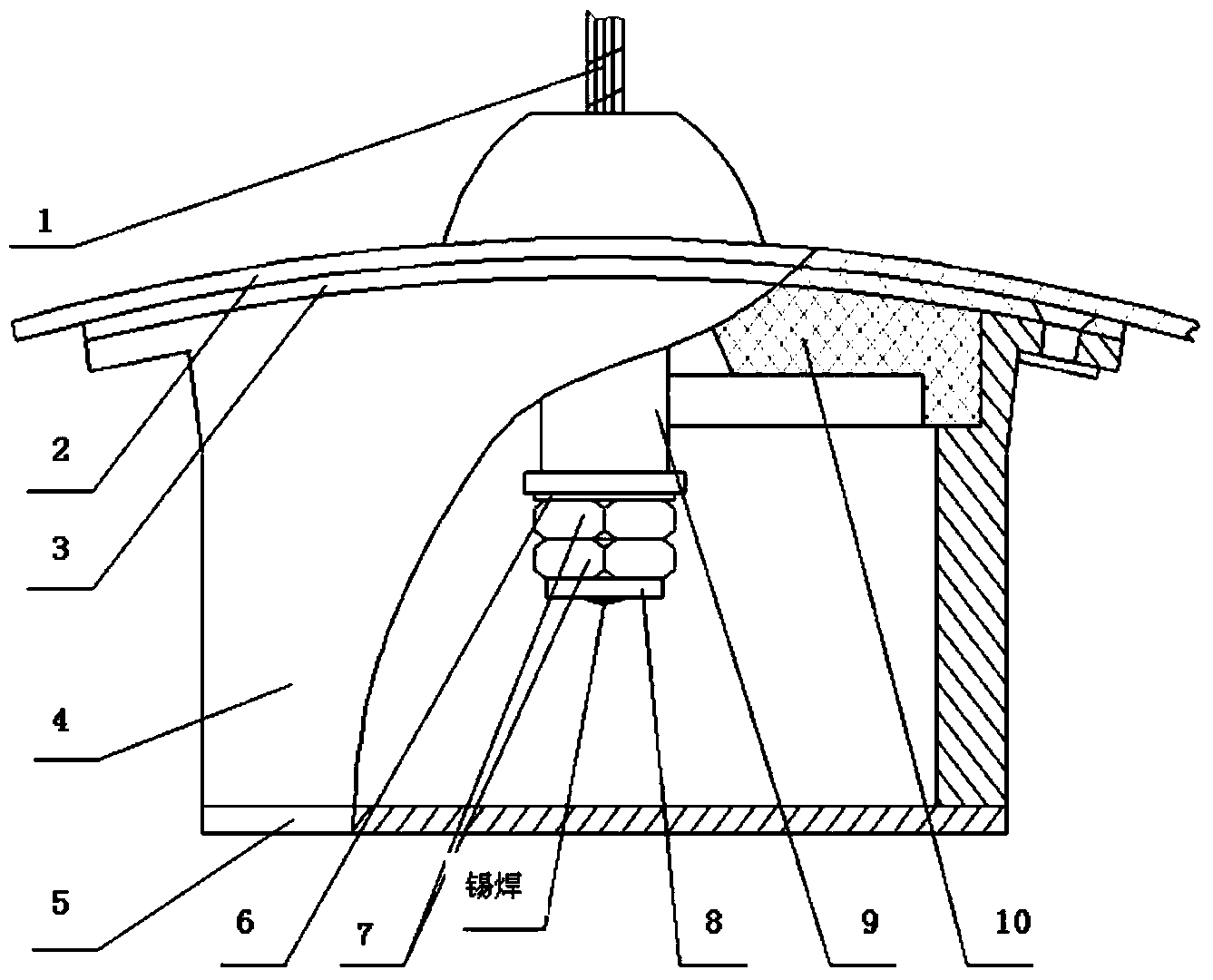
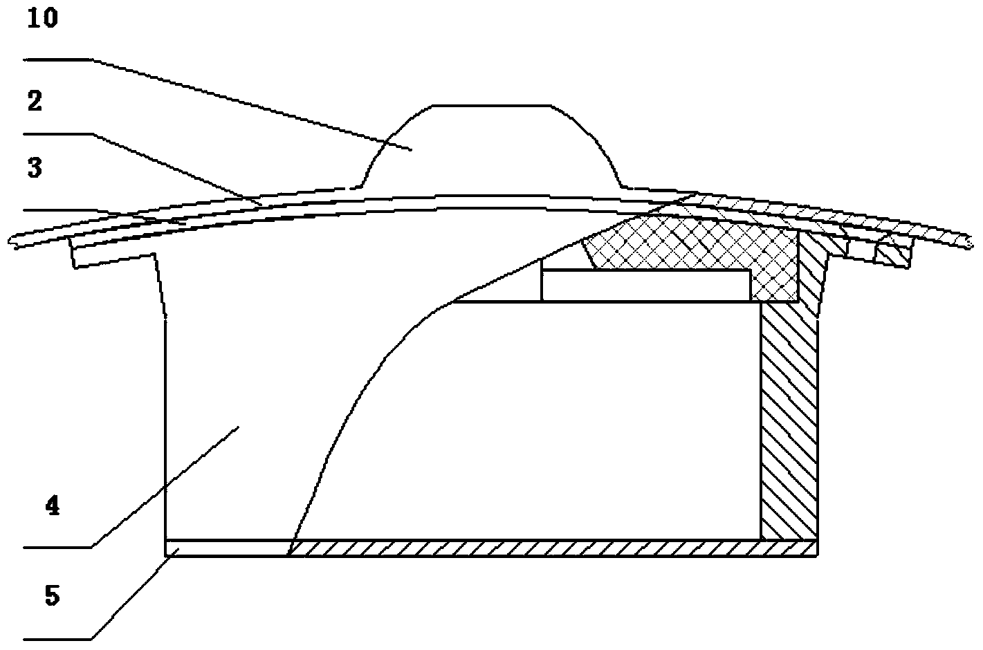
[0029] Please refer to Figure 1 to Figure 6 As shown, the airborne remote control antenna installation device of the present invention includes an antenna fixing device and an antenna installation matching box assembled with the antenna fixing device.

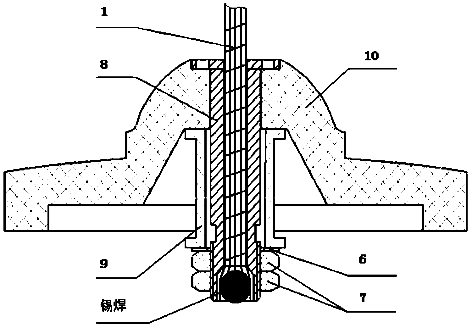
[0030] The antenna fixing device includes an antenna cable 1, a hollow screw rod 8, a bushing 9, a connecting piece 6, a double nut 7 and an insulating seat 10, etc. The hollow screw 8 includes a screw through hole 4 and a screw end opening 17 formed at the end of the screw through hole 4, the antenna cable 1 is inserted into the screw through hole 4 and the end of the antenna cable 1 is welded in the screw end opening 17, The bushing 9 is installed on the periphery of the hollow screw 8 and attached to the insulating seat 10. The connecting piece 6 is pasted on the bushing 9 and fixed by double nuts 7. That is, the penetration sequence of the hollow screw 8 is the insulating seat 10. , bushing 9, connecting piece 6 and doubl...


PUM


Abstract

The invention provides an airborne remote antenna mounting device which includes an antenna fixing device, an antenna mounting matching box and a special spanner. The antenna fixing device includes an antenna steel rope, a hollow screw, a bush, a connecting piece, a double nut and an insulating base; the antenna steel rope is inserted into a screw through hole and a tail end of the antenna steel rope is welded inside a tail end opening of the hollow screw; the connecting piece is tightly fixed on an insulating seat through the bush and the double nut; the antenna mounting matching box comprises an antenna matching box cover plate, an antenna matching box shell, an antenna matching box bottom plate and the insulating base; the antenna matching box cover plate is arranged above the antenna matching box shell; the antenna matching box bottom plate is arranged below the antenna matching box shell with use of a blind hole; and the special spanner comprises a handle, a groove, a convex column, and is used to prevent the hollow screw from rotating in tightening the double nut. The airborne remote antenna mounting device of the invention is capable of overcoming such defects in the airborne remote antenna mounting process that the space position is small and the antenna steel rope is easily disengaged under the external force.

Description

technical field [0001] The invention relates to an airborne remote control antenna installation device, which belongs to the field of mechanical design. Background technique [0002] Chinese patent application CN201010522374.1 discloses a steel cable fixing buckle, which adopts a steel cable fixing buckle, which is composed of splints and bolts, and the opposite sides of the two splints have strip grooves for accommodating the steel cables , the two splints have corresponding screw holes, and the bolts pass through the corresponding screw holes to make the two splints clamp the steel cables. In this patent, the steel cable fixing buckle adopts the smooth strip groove on the surface of the splint to contact the steel cable, and then uses bolts to fix the two splints, which avoids the contact between the bolt and the steel cable and damages the steel cable, and the appropriate length of the splint can also ensure that the steel The connection strength of the cable. But in th...

Claims


Application Information

Patent Timeline
Patent Type & Authority Applications(China)
IPC IPC(8): H01Q1/12
Inventor 王少云王洪宪王阳
Owner NANJING UNIV OF AERONAUTICS & ASTRONAUTICS
Why Eureka
Try Eureka