Base made of composite materials and manufacturing method thereof

A technology of composite materials and bases, which is applied in the direction of antenna supports/installation devices, etc., can solve the problems of satellite antennas such as low reliability, low axial stiffness, and poor thermal stability, and achieve excellent dimensional stability and axial stiffness High, good thermal stability

Active Publication Date: 2014-03-26
XIAN AEROSPACE COMPOSITE MATERIALS INST
View PDF4 Cites 6 Cited by
  • Summary
  • Abstract
  • Description
  • Claims
  • Application Information

AI Technical Summary

Problems solved by technology

[0003] The base of the bearing tube of existing satellite antennas is generally made of metal materials, which not only increases the negative mass, but also has the disadvantages of low axial stiffness and poor thermal stability in space high and low temperature environments; resulting in low working reliability of satellite antennas

Method used


Image

  • Base made of composite materials and manufacturing method thereof
  • Base made of composite materials and manufacturing method thereof
  • Base made of composite materials and manufacturing method thereof

Examples


Embodiment 1

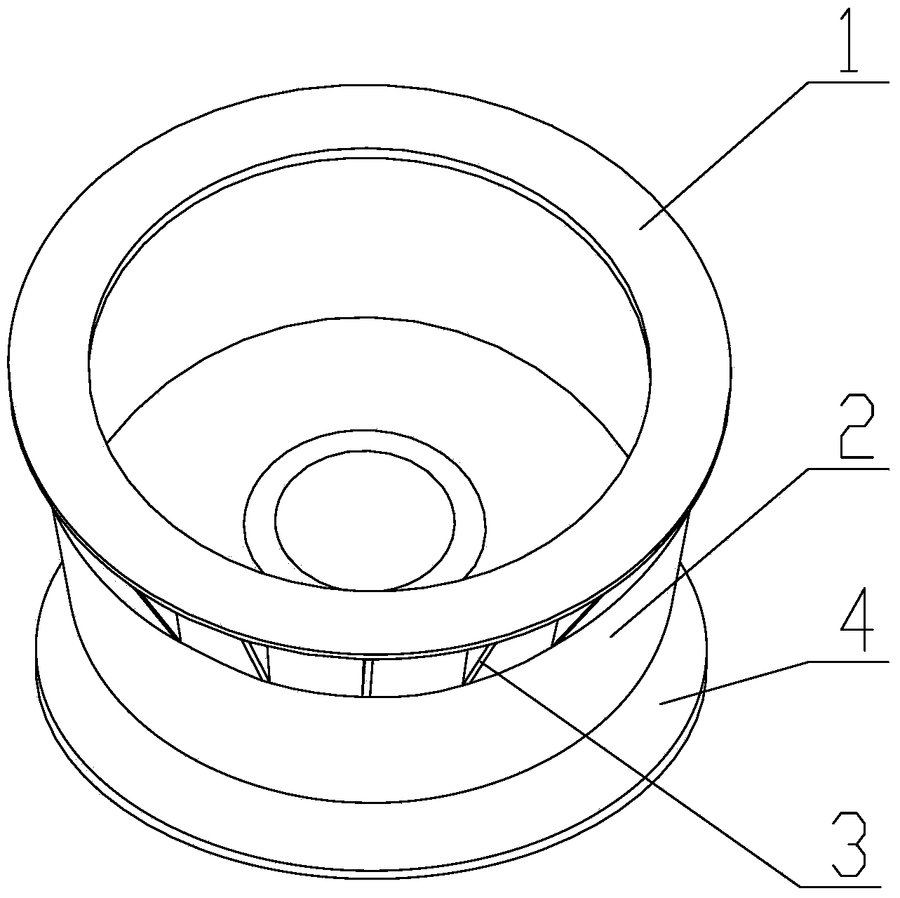
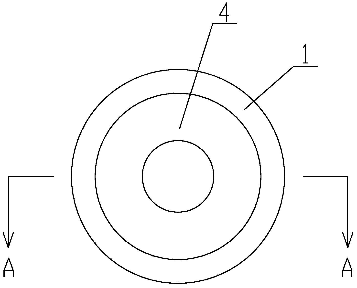
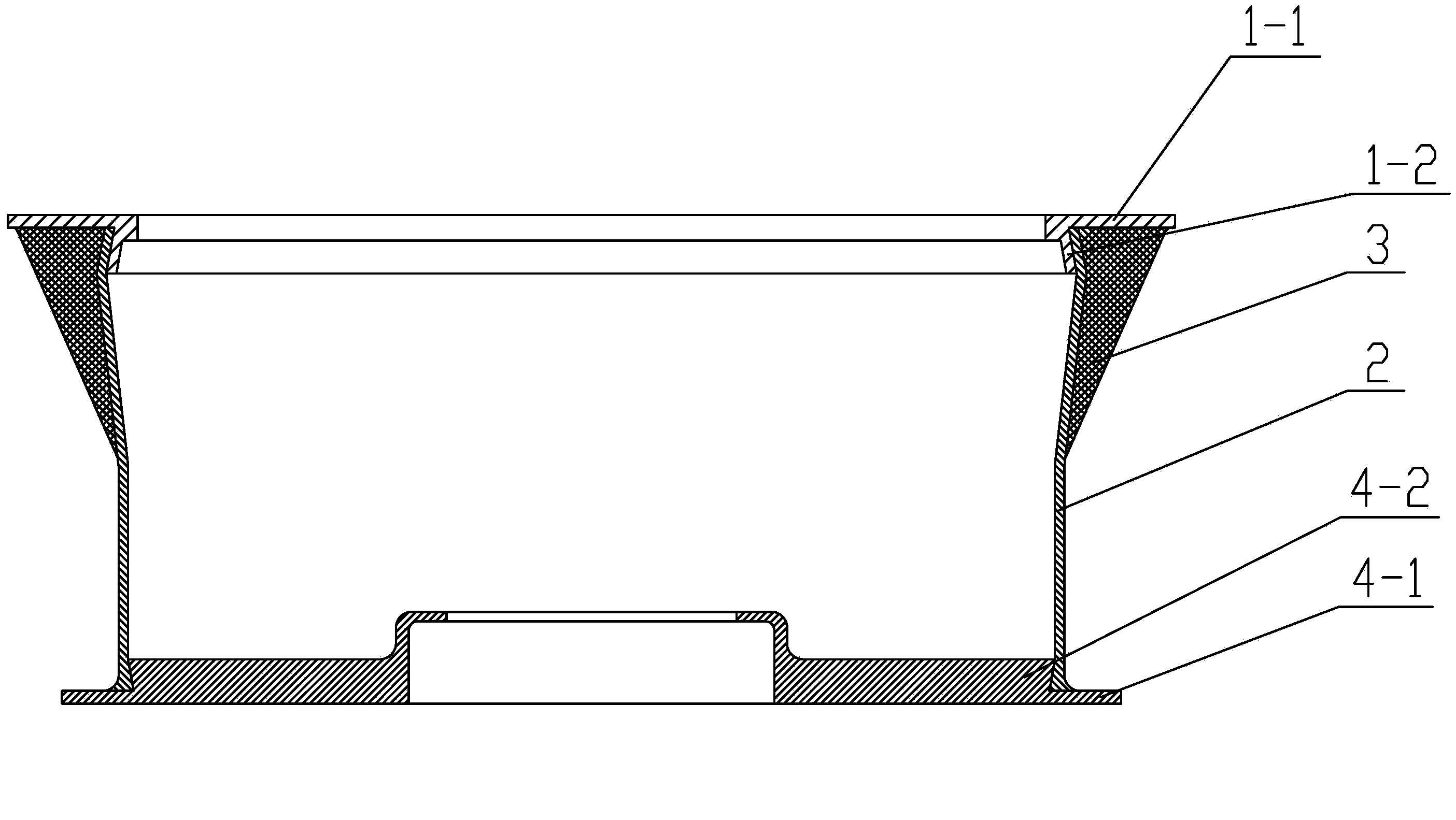
[0035] like figure 1 , figure 2 and image 3 As shown, the composite material base of this embodiment includes an upper end cover 1 and a lower end cover 4, and the upper end cover 1 includes a circular upper end cover body 1-1 and an upper and lower lower end cover body 1-1 arranged below the upper end cover body 1-1. A large first cone 1-2, the lower end cap includes a lower end cap body 4-1 and a second cone 4-2 with a large top and a small bottom arranged above the lower end cap body, the upper end cap body 1-1 Integral structure with the first cone 1-2, the lower end cover body 4-1 and the second cone 4-2 integral structure, the cylinder 2 is arranged between the upper end cover 1 and the lower end cover 4 , the upper inner wall of the cylinder 2 is closely matched with the outer wall of the first cone 1-2, the lower inner wall of the cylinder 2 is closely matched with the outer wall of the second cone 4-2, and the upper end cover 1 is below and A reinforcing rib 3 is...

Embodiment 2

[0050] like figure 1 , figure 2 and image 3 As shown, the structure of the composite base of this embodiment is the same as that of Embodiment 1, and the difference lies in: the angle between the conical surface of the first cone 1-2 and the vertical direction and the angle between the second cone 4 The included angle between the conical surface of -2 and the vertical direction is 2 degrees; the number of the reinforcing ribs 3 is 16.

[0051] This embodiment requires the preparation of a base with the following dimensions: the outer diameter of the upper end cover body 1-1 is 300mm, the inner diameter is 200mm, the outer diameter of the lower end surface of the first cone 1-2 is 250mm, and the inner diameter is 220mm, and the upper end cover 1 The height is 15mm, the outer diameter of the lower end cover body 4-1 is 280mm, the outer diameter of the upper end surface of the second cone 4-2 is 240mm, the overall height of the lower end cover 4 is 10mm, the thickness of the ...

Embodiment 3

[0061] like figure 1 , figure 2 and image 3 As shown, the structure of the composite base of this embodiment is the same as that of Embodiment 1, and the difference lies in: the angle between the conical surface of the first cone 1-2 and the vertical direction and the angle between the second cone 4 The included angle between the conical surface of -2 and the vertical direction is 10 degrees; the number of reinforcing ribs 3 is 10.

[0062] This embodiment requires the preparation of a base with the following dimensions: the outer diameter of the upper end cover body 1-1 is 400mm, the inner diameter is 300mm, the outer diameter of the lower end surface of the first cone 1-2 is 350mm, and the inner diameter is 320mm, and the upper end cover 1 The height is 20mm, the outer diameter of the lower end cover body 4-1 is 380mm, the outer diameter of the upper end surface of the second cone 4-2 is 340mm, the overall height of the lower end cover 4 is 15mm, the thickness of the cyl...


PUM


Abstract

The invention discloses a base made of composite materials. The base comprises an upper end cover and a lower end cover. The upper end cover comprises an upper annular end cover body and a big-end-down first cone arranged below the upper end cover body. The lower end cover comprises a lower end cover body and a big-end-up second cone arranged above the lower end cover body. A cylinder is arranged between the upper end cover and the lower end cover. The inner wall of the upper portion of the cylinder is in close fit with the outer wall of the first cone, and the inner wall of the lower portion of the cylinder is in close fit with the outer wall of the second cone. A reinforcing rib is arranged at the position, below the upper end cover, on the outer side of the cylinder. The upper end cover, the cylinder, the reinforcing rib and the lower end cover are all made of composite materials. In addition, the invention further discloses a manufacturing method of the base made of the composite materials. All the portions of the base made of the composite materials are made of the composite materials, and the base made of the composite materials has the advantages of being high in axial rigidity, good in heat stability under the space high-low temperature environment, small in negative quality, high in modularization degree, good in reliability, excellent in overall performance and the like.

Description

technical field [0001] The invention belongs to the technical field of composite materials, and in particular relates to a composite material base and a preparation method thereof. Background technique [0002] The base of the satellite antenna bearing tube is an important installation carrier for satellite antenna positioning. Therefore, the base needs to withstand the large overload caused by the complex mechanical environment in the stages of satellite launch, maneuvering, and orbit change; it must also have excellent dimensional stability in the high and low temperature environment of space to ensure the normal operation of the antenna. [0003] The base of the supporting tube of the existing satellite antenna is generally made of metal materials, which not only increases the negative mass, but also has the disadvantages of low axial stiffness and poor thermal stability in space high and low temperature environments; resulting in low reliability of the satellite antenna....

Claims


Application Information

Patent Timeline
Patent Type & Authority Applications(China)
IPC IPC(8): H01Q1/18
Inventor 廖英强曾金芳刘小建景宽周伟江方毅徐新山张润阳胡涛李锵李翠云
Owner XIAN AEROSPACE COMPOSITE MATERIALS INST
Why Eureka
Try Eureka